
Savor our FTC disclosure's epic tale here ...
Suzuki GSX-8R Valve Check & Shim Clearance Calculation
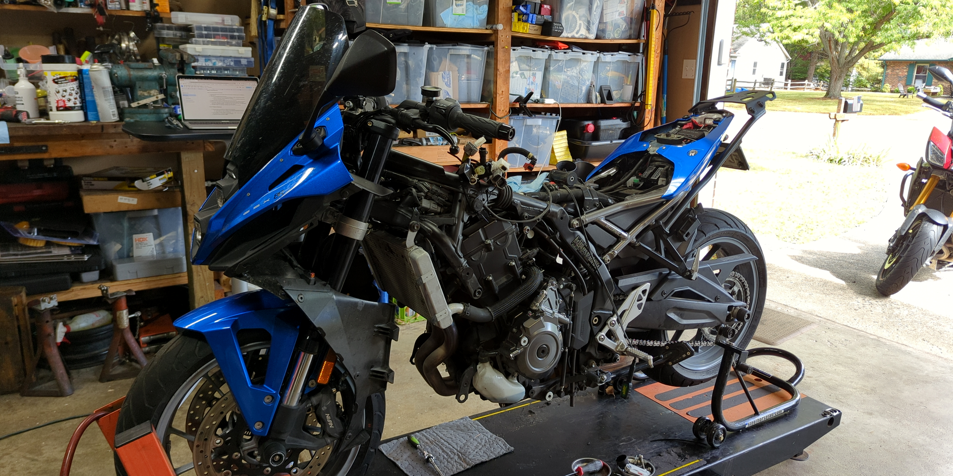
I bought the GSX-8R, so this valve check guide naturally starts with GSX-8R plastic surgery before it gets to the parallel-twin business end. The useful bit is that Suzuki's 776 cc 270 DOHC parallel twin also lives under the GSX-8S, GSX-8T, GSX-8TT and V-Strom 800 family so once your own bodywork/tank/radiator path is handled, the clearance check, shim math and reassembly logic should still earn its keep. If you're here for the engine work and not my fairing origami, read the table of contents and jump around as you see fit.
“Our GSX-8R valve check guide walks through the parts, tools, shim math and reassembly notes to make Suzuki’s parallel twin easier to service.”
Because it's a parallel twin, one may assume the GSX-8R valve check to be a simple process and in hindsight, it is. But that first go might present hangups, those itemized pre-prep preparatory preparations that jacket our mental chalkboards with useless, self-inflicted intimi-jargon. This is especially true when crammed into a limited timeframe, in my case a single day after which the bike had somewhere to be.
Having measured shim clearance myself on every bike before it, I found the GSX-8R valve check offers an equal-size menu of positives and negatives. Weighed against my Bandit 1200, some motions are easier than before while others offer a creative opportunity for new swear words. Neither comes with an open-source how-to on getting it done efficiently.
Modern tech in the GSX-8R makes for one heck of a ride! As it's what I'll call "compact biggish" (approaching liter displacement on a stressed-member frame), stuffing a liquid-cooled 270° engine and its exploded laptop's worth of ECU into a sleek tra(ck)xedo means far less wiggle room for 'Mercan size sandwich clamps (er, um ... hands).
The good news is that, with the right parts and tools at the ready, all of this is quite easy. That is, so long as wrenchers observe each individual step in these instructions and avoid shortcuts. What might appear to be a more efficient path can fast become a back alley rabbit hole.
So, before we begin to begin, do at least one of the following:
- Buy the Suzuki Factory Service Manual
- Order the Suzuki Factory Service Manual
- Purchase the Suzuki Factory Service Manual
Dat Dare Wallet
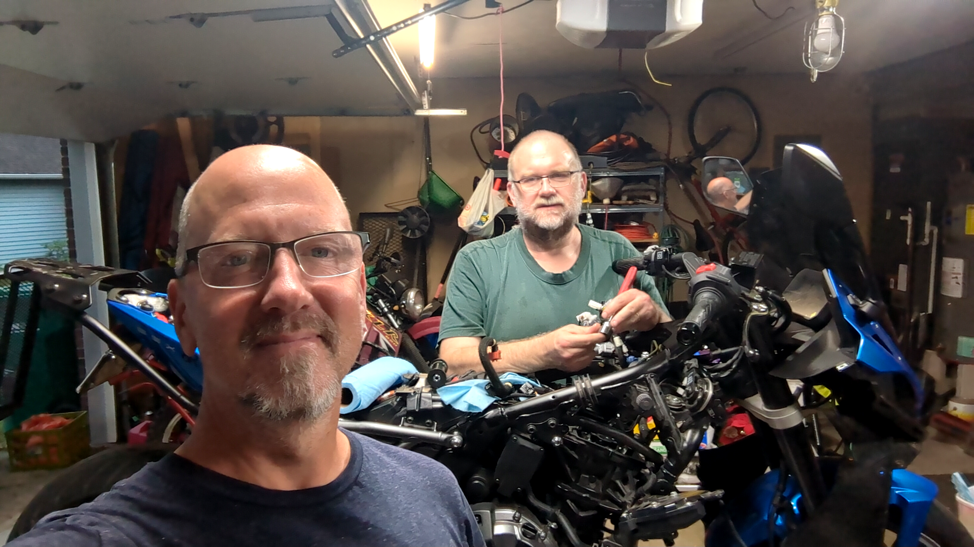
Because the bike before this was an R1200RS, my first time goin' at a GSX-8R warrants a Japanese refresher course. Enlisting the help of TRO author and Radio TRO co-host Brian Wringer was a no-brainer. He immediately dove into the online parts fiche, confirming and itemizing a few details (bust out your billfold).
Dem Dare Parts
The GSX-8R valve check is no different from any other in that the shim kit comes first. Both intake and exhaust for El Gixxator are 9.48 mm diameter. Then there's the matter of two seals under the valve cover and two o-rings under the cam caps, not to mention spark plugs and their relevant seals to be replaced.
Prior experience would suggest the valve cover perimeter gasket can be reused once or twice at least. The spark plug seals tend to get crushed and must be replaced. The valve cover gasket is inexpensive, so no harm in replacing that as well instead of taking chances.
If the camshafts need to come out, there are also two o-rings under the camshaft caps. O-rings cannot be re-used, so have these in hand. While you're in the neighborhood, replacing the spark plugs is required.
Part of the process may involve removing the cam chain tensioner. There are two gaskets there as well. Also, the o-ring and plug gasket should be replaced on the magneto cover.
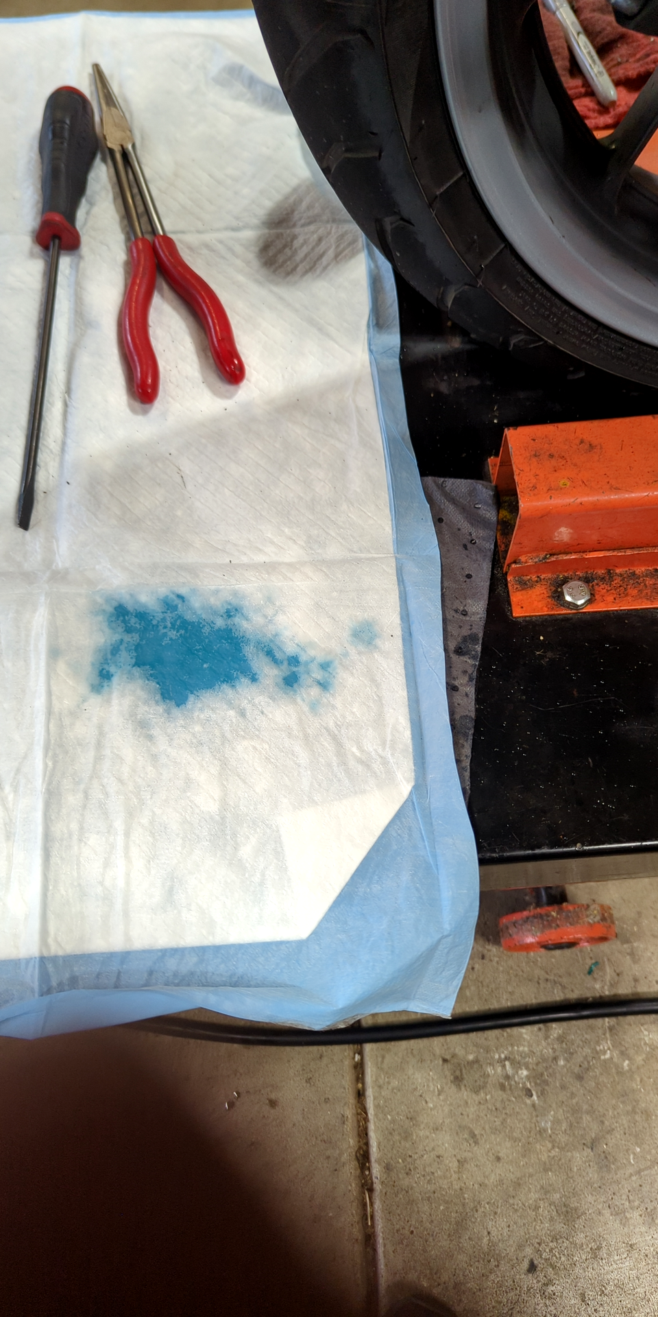
The radiator will need to be drained. Best to have Suzuki's magical blue-green coolant elixir on hand. If you're as prone to spilling fluids on your friend's garage floor as yours truly, you're gonna need it.
Parts List
- shim kit, 9.48 mm
- valve cover perimeter gasket (#2, x1)
- valve cover seals (#5, x2)
- cam cap o-rings (#4, x2)
- spark plugs (#12, x2)
- cam chain tensioner gaskets (#9 and #10, x1)
- magneto cover o-ring and others (#7, #8 and #14)
- Suzuki Ecstar Super Long Life Coolant 990A0-02E00-01Q
- push pin rivets (spares)
If you review the GSX-8R valve check instructions carefully, you'll find most of the mentioned parts/gaskets/seals/fluids should be replaced to do the job right. If you don't have them ... probably better to order and wait. Schedule the entire process around their arrival.
Dem Dare Tools
I gotta hand it to Suzuki. This latest generation flock comes with a number of combo bolts that two tools can access. The engine covers, for example, are box-head and Torx. In the grander scheme of things, though, this bike has at least one of every fastener known to man. I wouldn't be surprised if when I go to change my fork oil I find dovetails and treenails for stanchions.
The following list is organized vaguely in order of use ...
Tool List
- page markers (multicolor adhesive)
- short and long metric hex sockets
- metric socket/wrench set
- shop towels
- long reach bent needle nose pliers
- zip ties (temporary, easy to spot neon green)
- dual lock tape
- metric feeler gauges
- open/ratchet box wrenches (metric combo)
- small telescopic magnet (pots)
- torque wrench set
- large puppy pads
Having the above list is one thing. Organizing the entire lot for grab 'n' go efficiency is another. The GSX-8R valve check is a little more involved with tools/bits/pieces than any household ice tray will allow, so rolling organization might be worth the investment.
Make Time³ For The GSX-8R Valve Check
In my own garage life, there've been several occasions where I've had no choice but to take a deep breath and hold it for the exact minimum, emergency-only allowable time duration of some complex wrenching task. Don't be that guy. Eye the odometer horizon and barter with your datebook accordingly.
A "comfortable" GSX-8R valve check means parts, tools and an excess of patience are all at the ready. It also means scheduling around experience level. First time? Avoid headache/pressure by setting aside a couple of days for calm, mild action. Next time and beyond, it'll take all of one day (likely less).
Point is, no amount of perfectly written website instructions will change that sense of urgency we all feel when pulling cams on an unfamiliar machine for the first time. Northern winter downtime is your friend. Southern rat bikes are another. Either way, a stress-free, learner-centric environment is worth a bit of calendar augmentation. Two days oughta be enough, breaks and all.
Prep For The GSX-8R Valve Check (Cover Access)
With the manual in front of you, choose two colors of page markers. Use the first color to bookmark pages 0B-6, 1D-14, 1F-8 and 1H-6. Use the other color to bookmark 9D-54, 9D-58, 9D-68 and 9D-84.
Our manual and its Kentucky fried recipe for success are dogeared. Every consumable part is sorted. Necessary tools are within reach. The bike's been cool for 12+ hours. There's plenty of time to patiently address every step.
Remove both seats, then disconnect and pull the battery: negative first, positive second.
Upper Plastics
The origami ain't bad! Of course, there's an order, but each piece removed more than simplifies the next. Yes, there are three (or four or five-teen) fastener types, namely push-pin connectors, Allen head and the occasional "miscellaneous".
Organizing the fastener jigsaw puzzle so there's no mix and match is a matter of personal preference. Overkill or not, small Ziploc bags and gaffer tape stuck to the component in question works. So does a bucket full of "deal with it later".
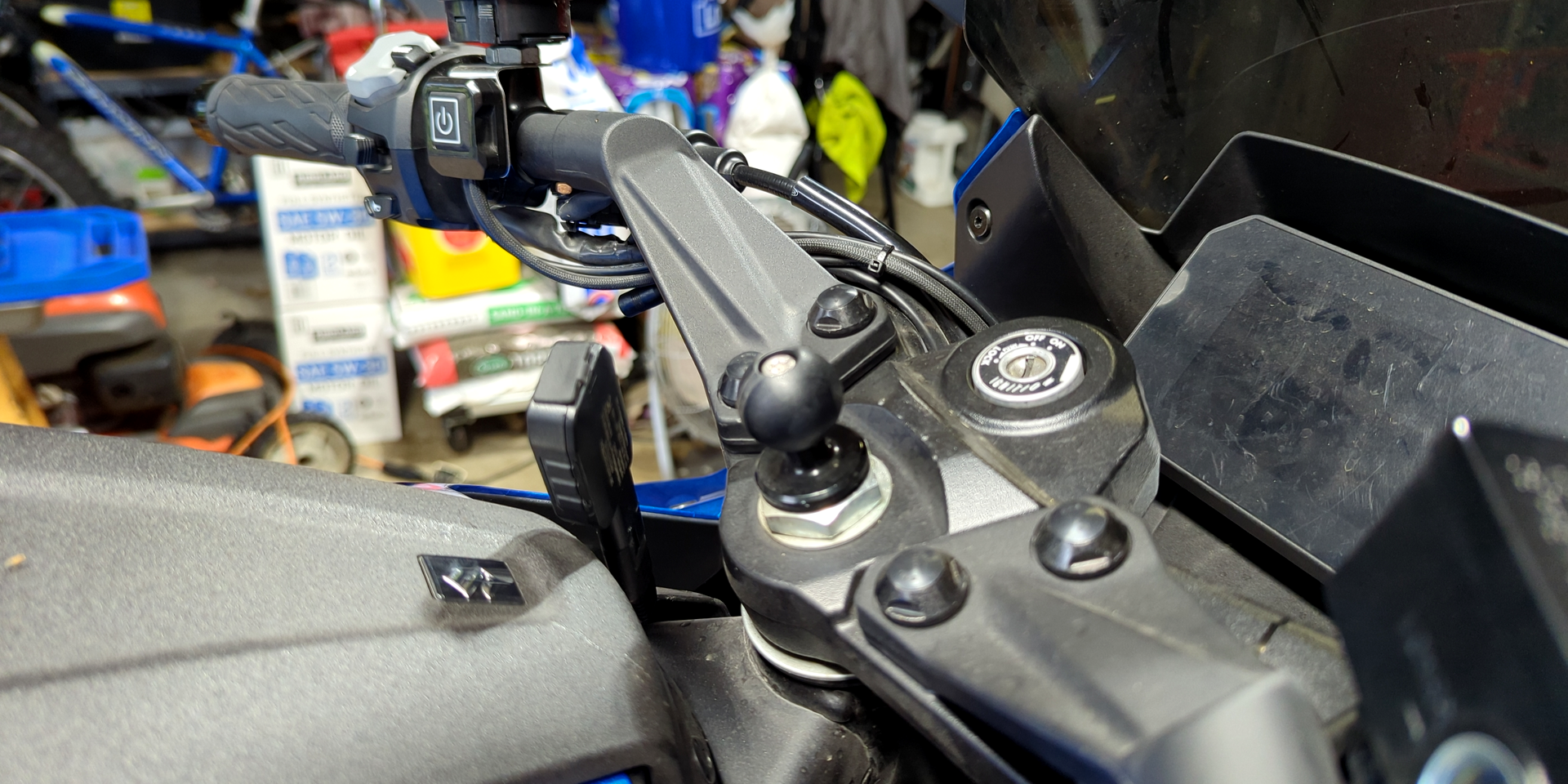
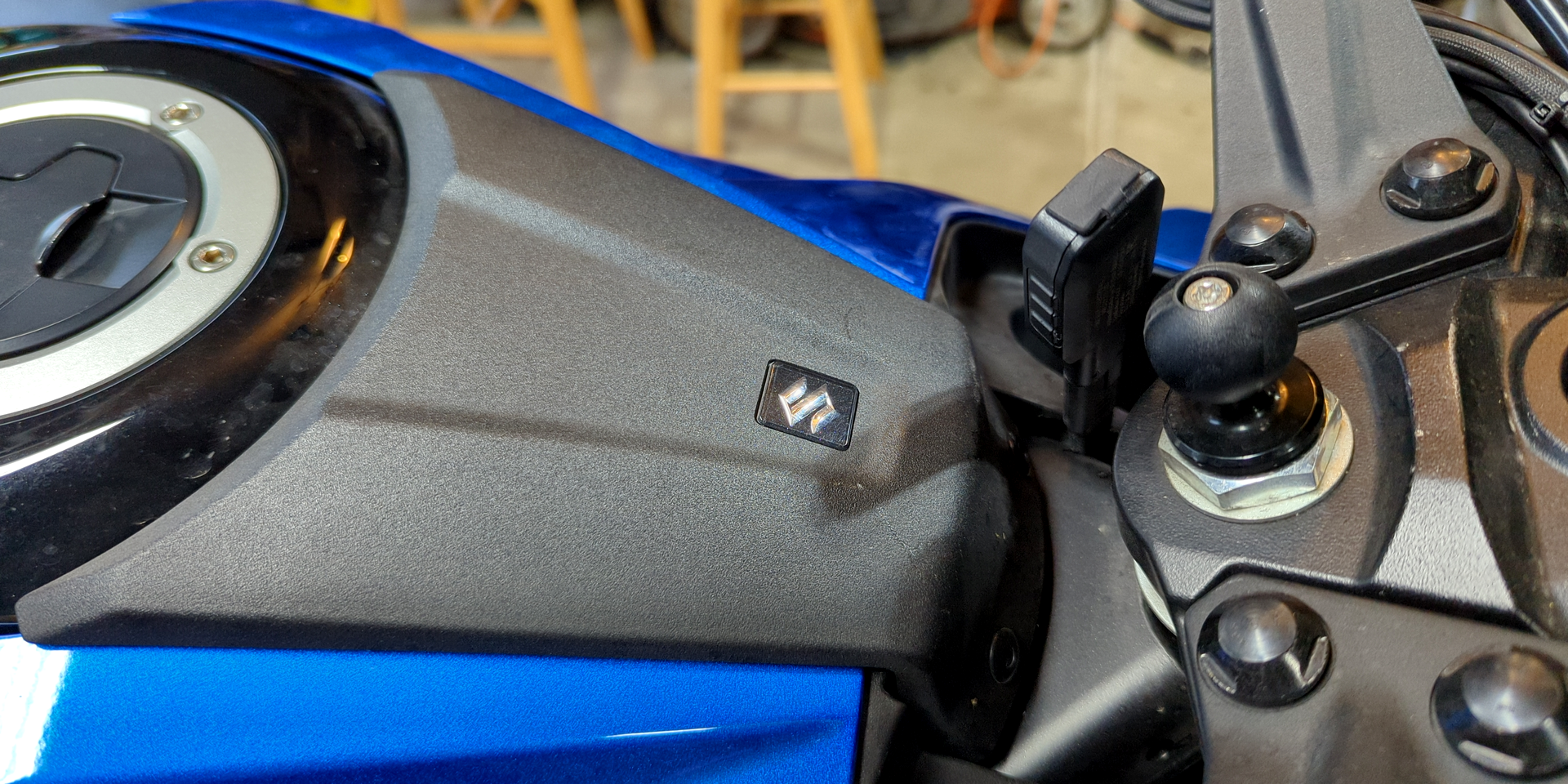
If there are any third-party obstructions, such as the RAM X-Mount I've installed at the steering stem, yank 'em and set aside.
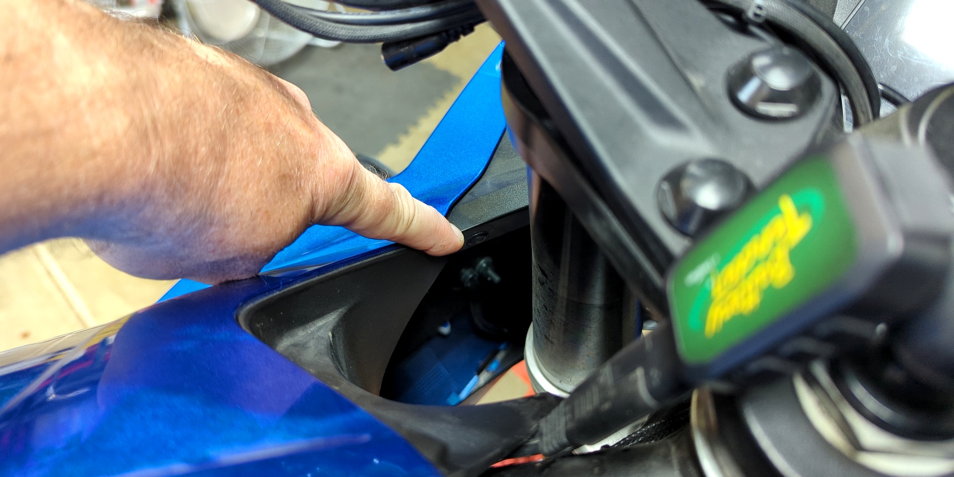
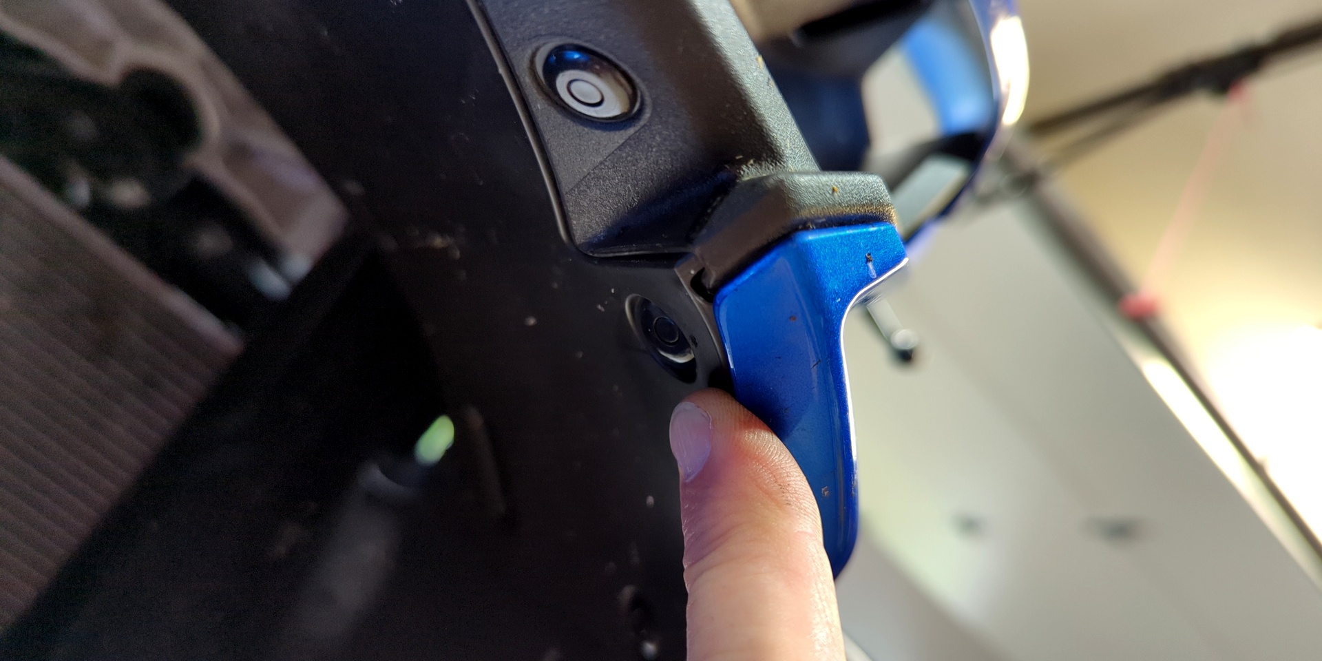
On what the fiche refers to as the "fuel tank front cover", there are two push-pin connectors toward the nose. For every stock push-pin connector on this bike, a #3 Allen key is our friend. Compress the inside dowel of each and extract, then slide the front cover forward to remove.
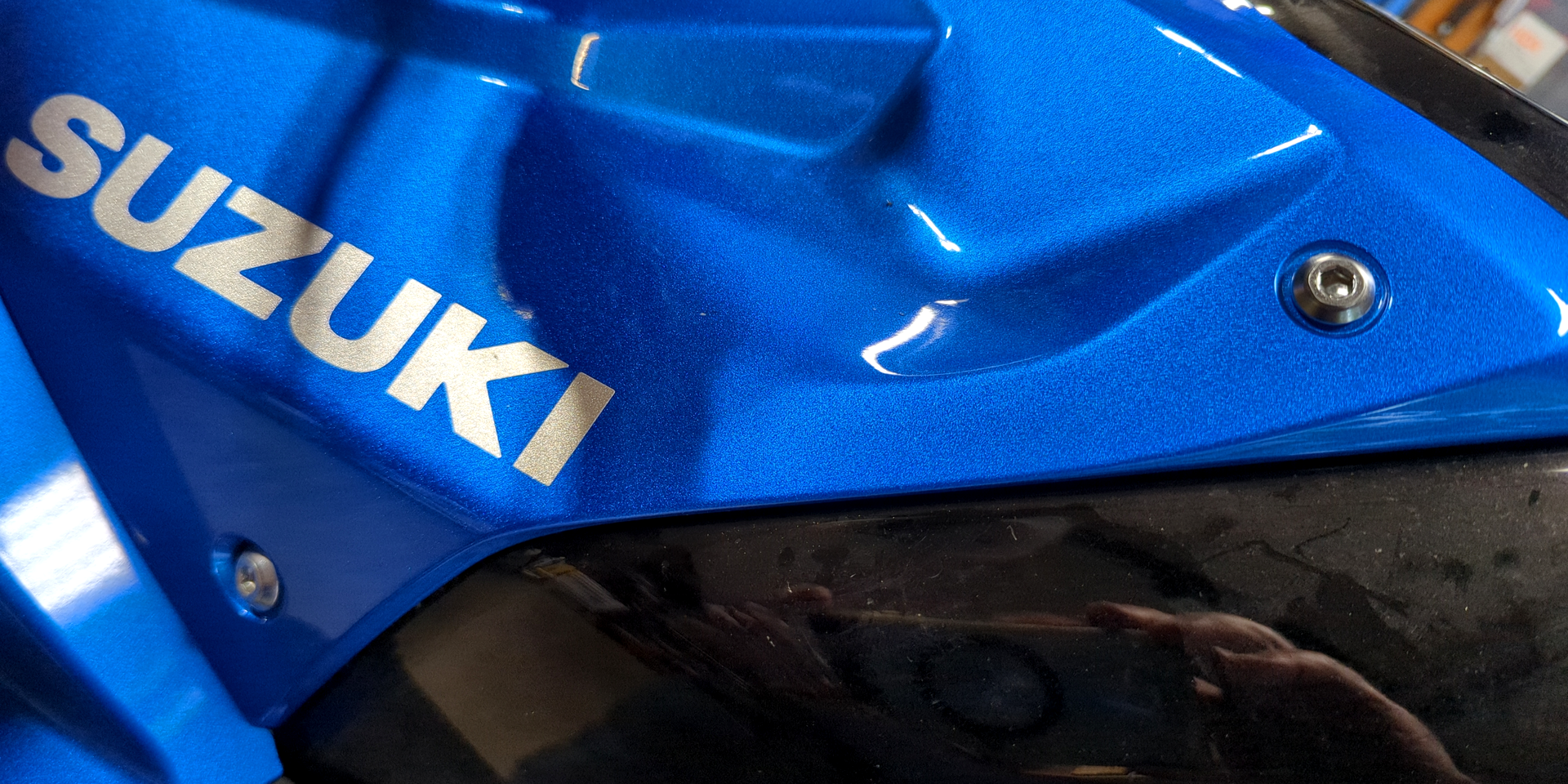
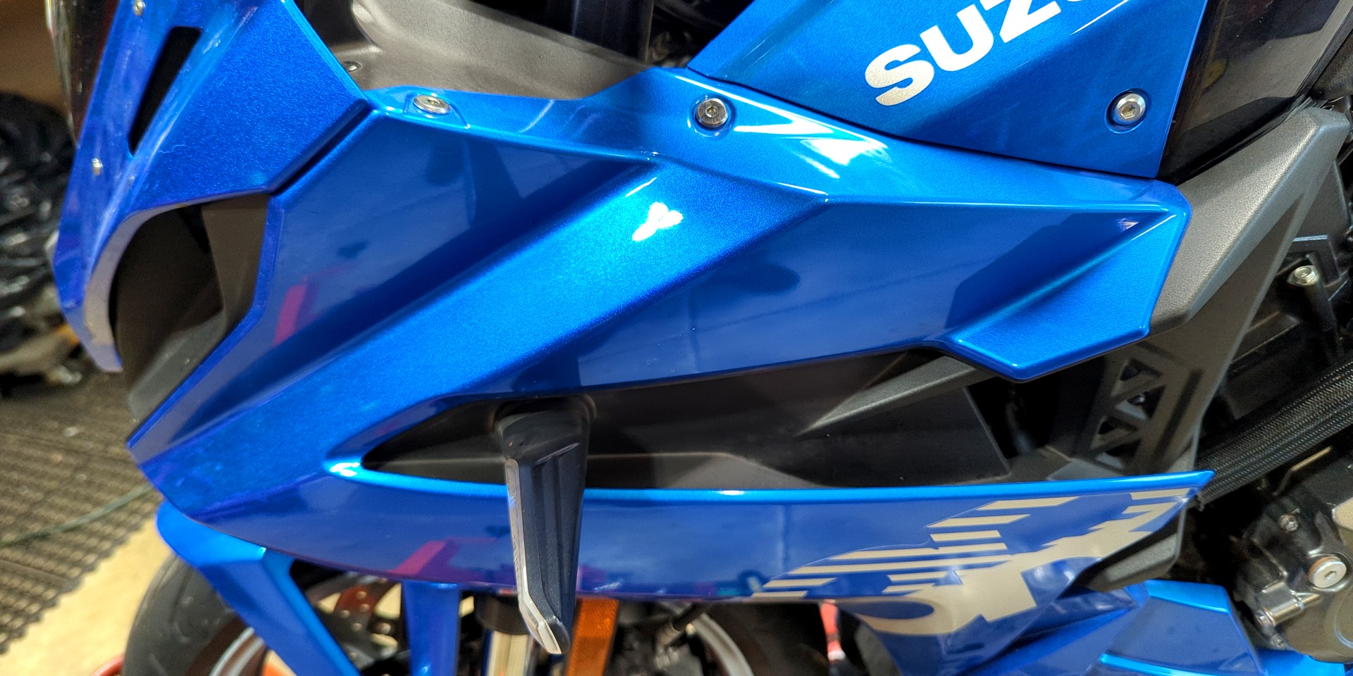
We're immediately ready to go big with the painted portions, namely the tank covers and side cowlings. For each tank cover, there's a push-pin connector + 5 mm Allen at the top/front. To the back, pull the polished 5 mm button-head Allens. Once these bolts and fasteners are removed, leave the tank covers in place. Similar fasteners on the cowling must be addressed before removing the tank covers.
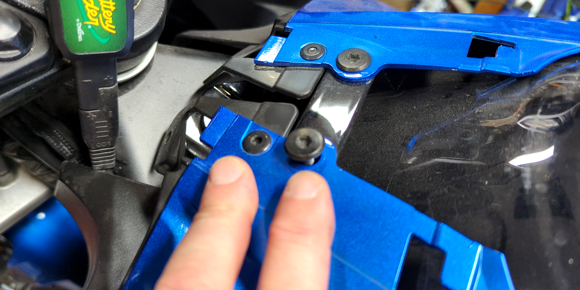
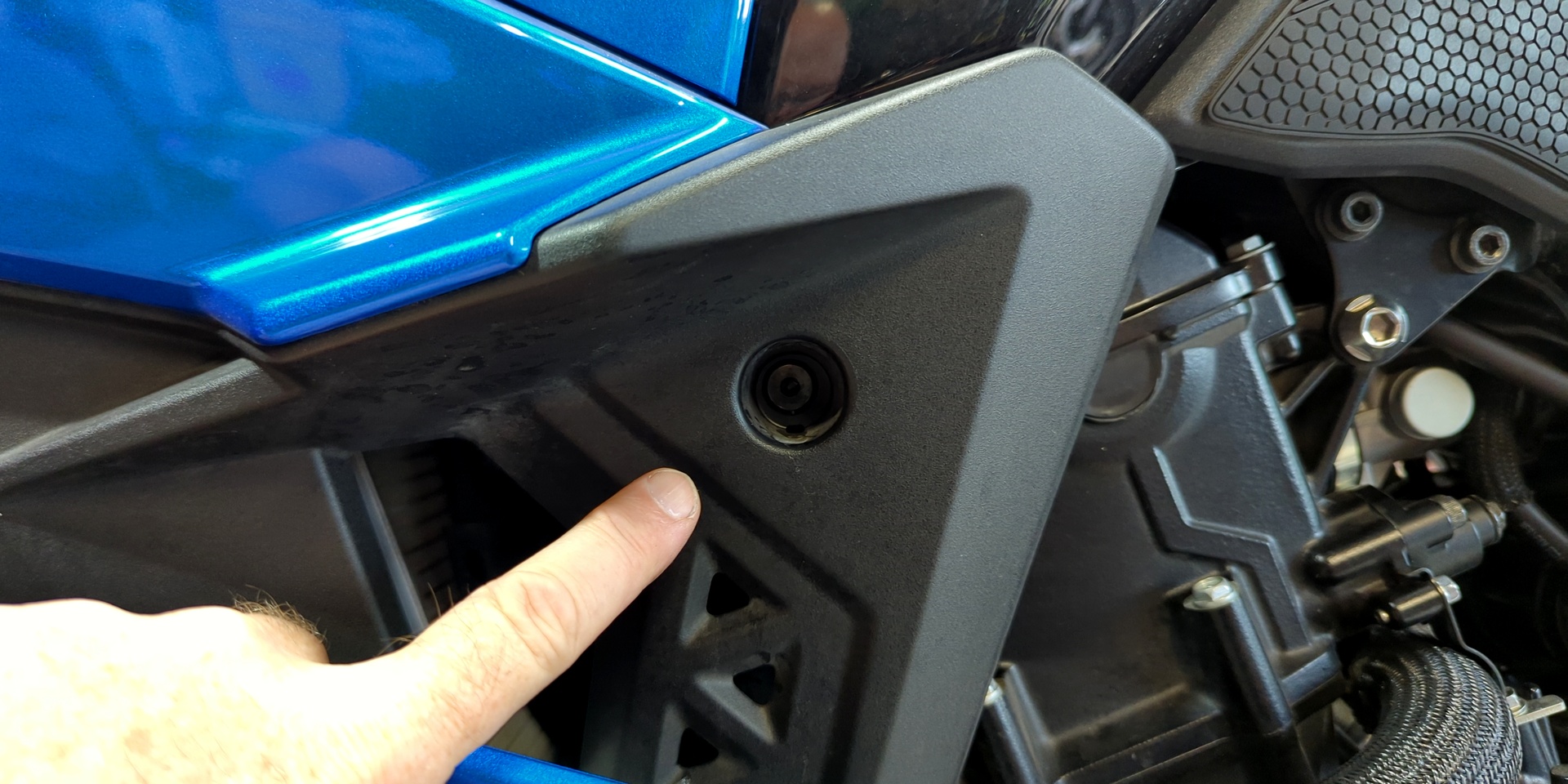
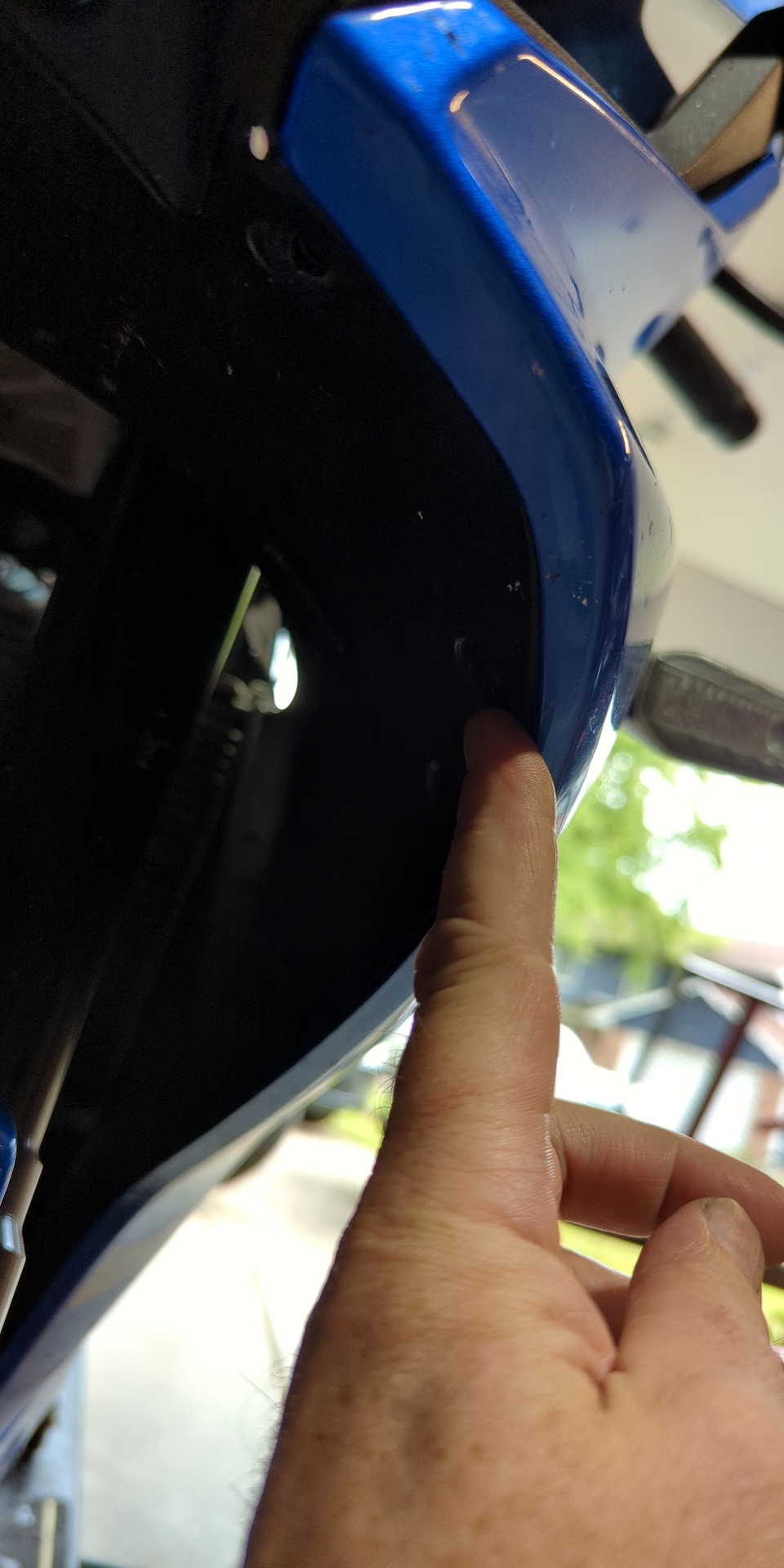
For each side cowling, there are two 4 mm Allens at the top, a well-hidden 4 mm Allen toward the center (black outlet) and stealthy push-pins hiding at the inside/top, under-nose (toward the outside) and inside cheek. Only remove the bolts/fasteners, leaving the cowling in place (we need to pop 'n' pull the tank covers first).
Use the left/right slideshow nav for visual steps ...
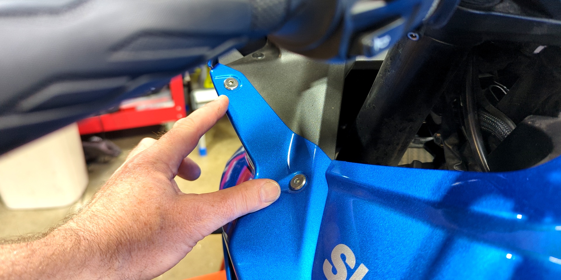
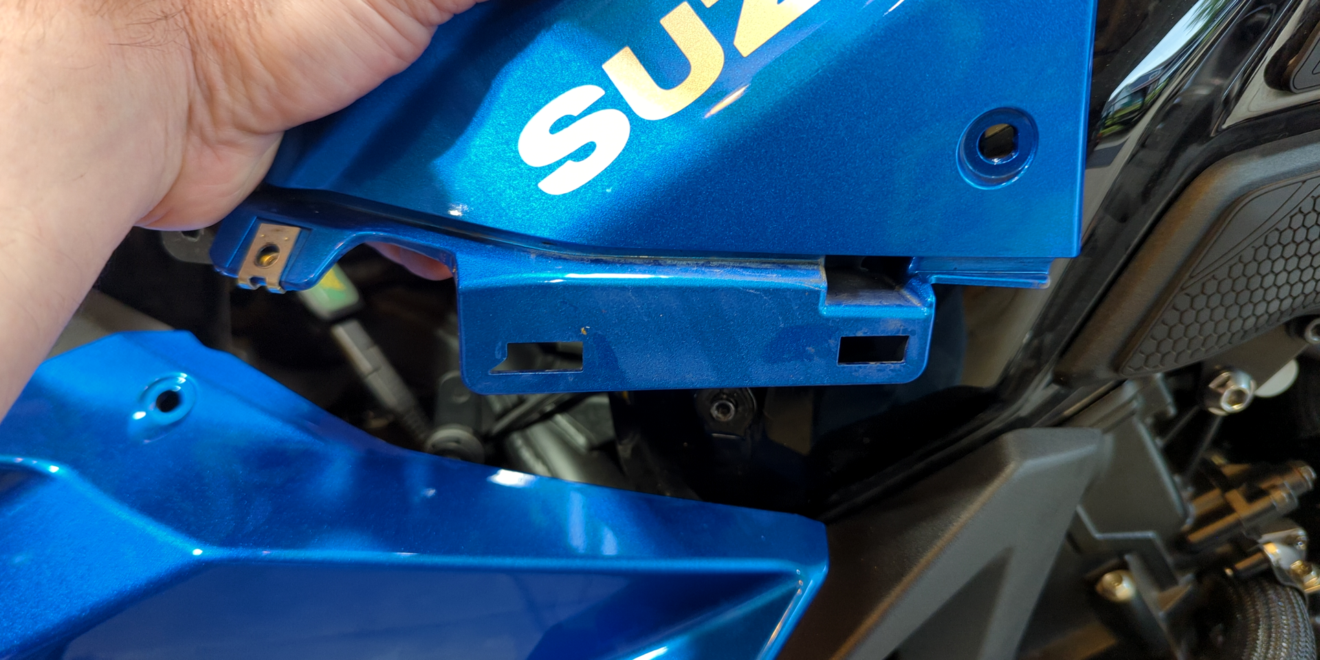
Let's remove the tank covers. First, unseat their upper outlets, namely the ones for the push pin / Allen combo as well as the 5 mm button heads. The button head outlets fit over an external collar that's part of the tank itself. Once unseated, pull the entire tank cover away from the bike. "Away" means left/right of rider and chassis, so if you're standing to the side of the bike, pull 'em toward you.
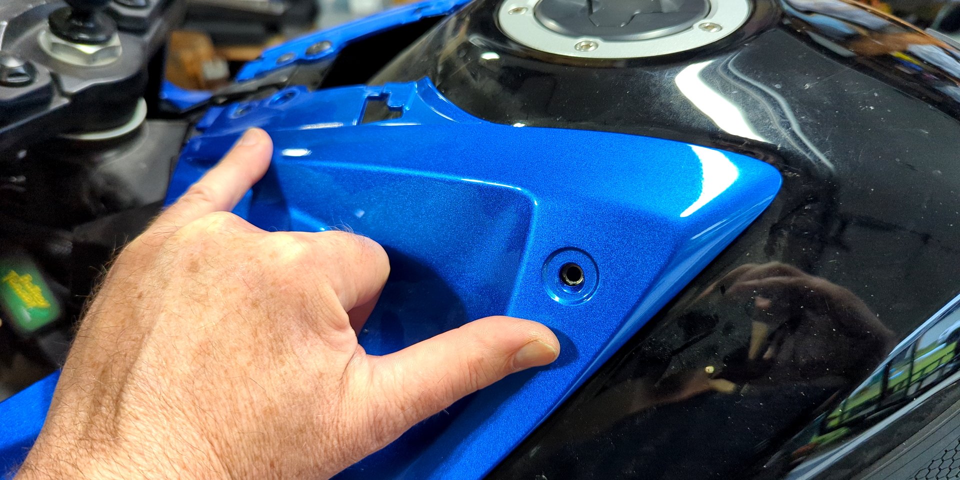
Once away from the tank, the cover will likely still be connected to the side cowling, which is fine. It'll just sort of float there, easy to wag left/right by hand. Now, flex the top of the side cowling away from the bike while pressing the base of the tank cover in the opposite direction. Light punches may help things pop apart. Note the shape of the outlets. There are no "hooks", just direct-out "buttons" that feel spring loaded. No biggie.
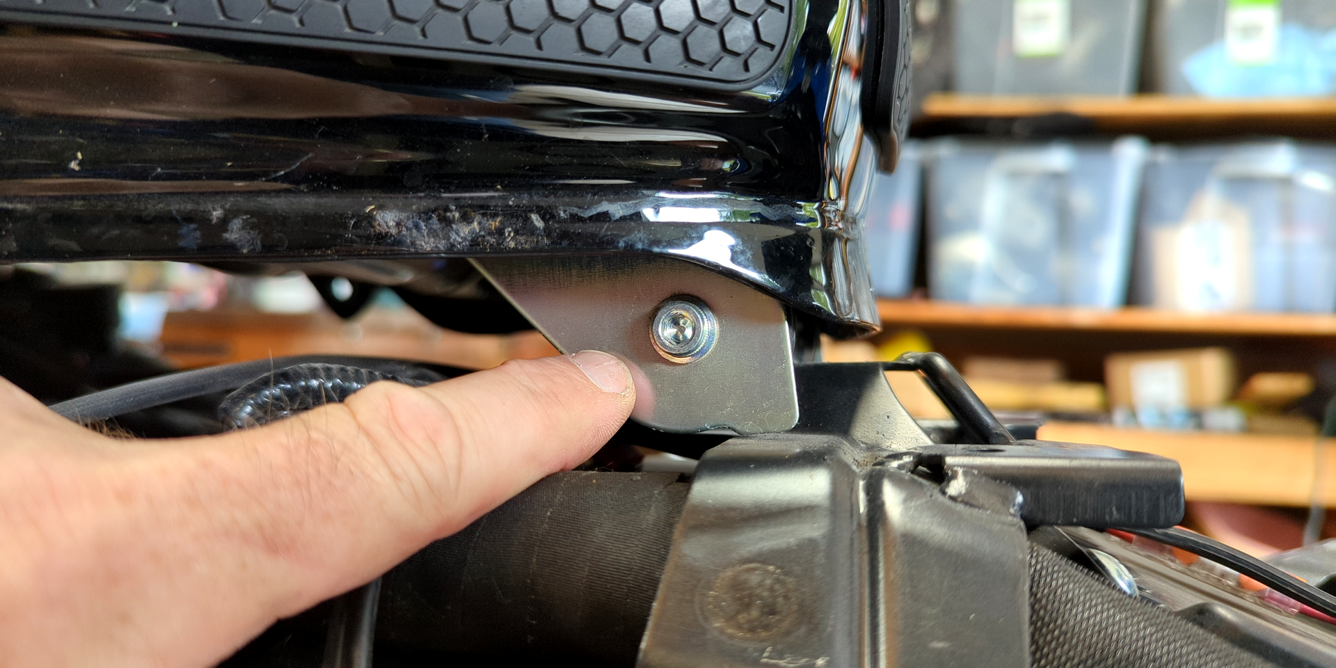
The only remaining plastics standing between us and the fuel tank are the knee huggers, located on both sides toward the base of the tank at the seat. These are held in place by a single pin, dual lock tape and material contour. Quick observation and some tugging gets it done, though you may need to replace the dual lock tape (or replace with your preferred alternative).
Fuel Tank
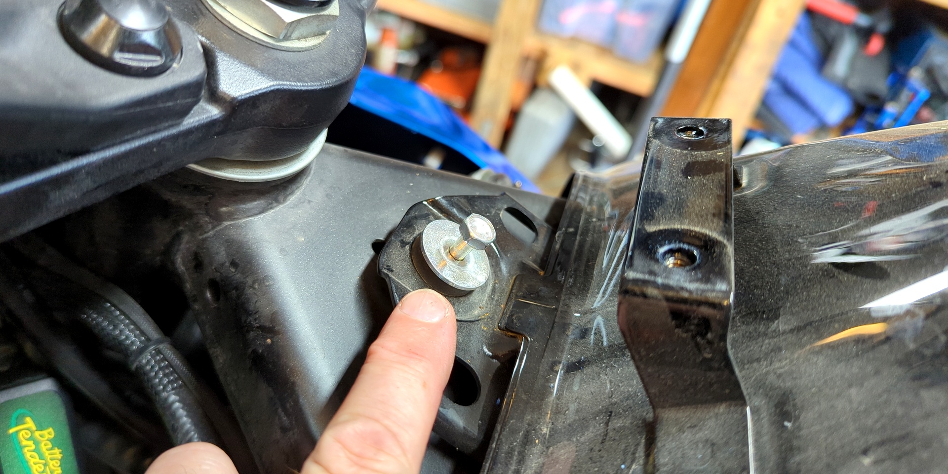
It's tank time. Unstrap the wire/hose guide to the left side underframe. Find yourself a 1' piece of wooden 2x4 and place it nearby. Remove the single, 10 mm front tank bolt (classic) and use the 2x4's lower/flatter side to raise it (2" rise). Place shop rags in garden-variety locations, then unclamp and disconnect the two smaller hoses. Note that the front hose has a silver dot and the rear, a small clamp. This is important for reassembly.
Use the left/right slideshow nav for visual steps ...
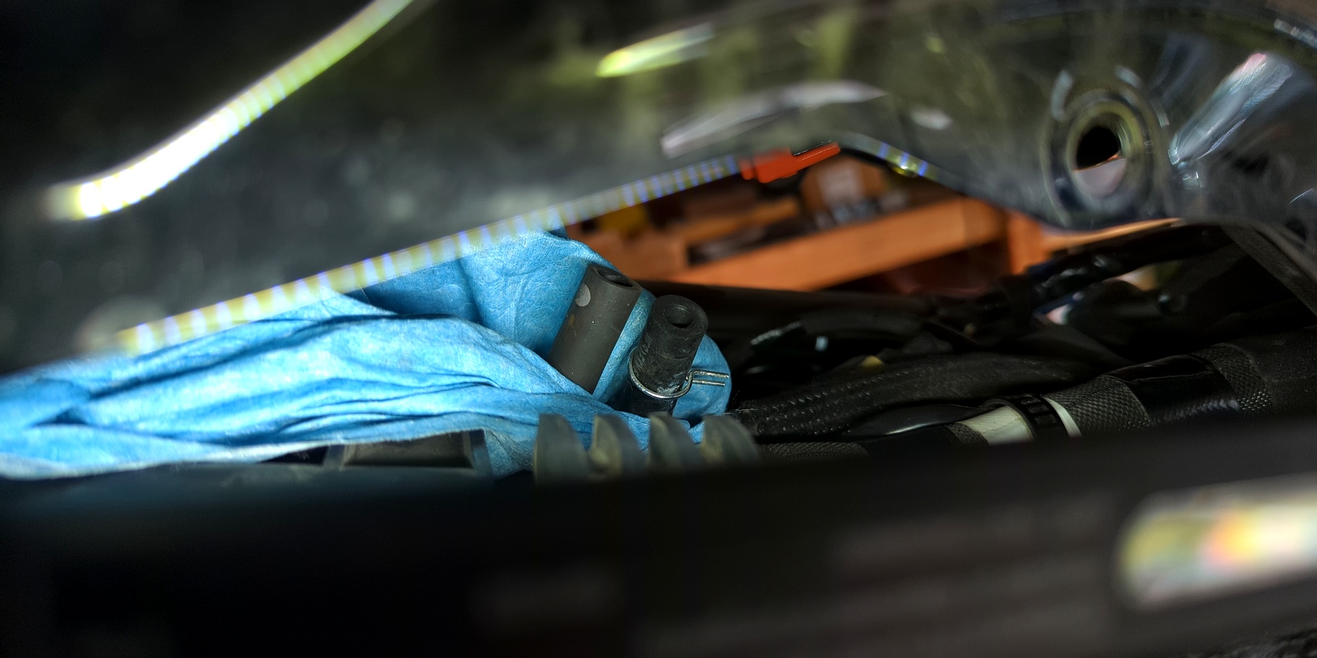
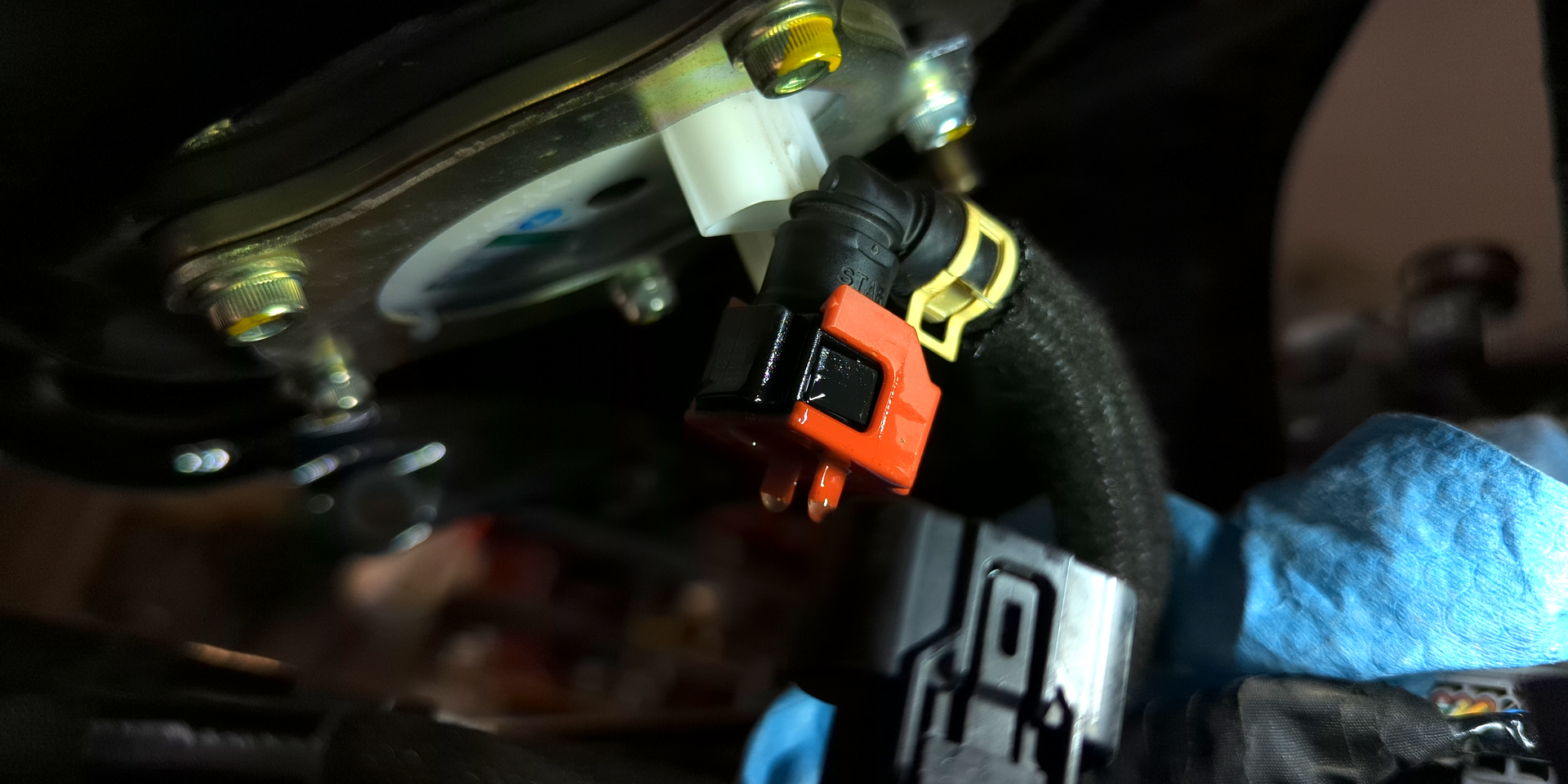
Now turn the 2x4 in place so that it's in its taller position (4" rise). Slide the fuel line's red plastic locking mechanism to the open position, then tug it from the L-shaped node. Now deal with the fuel pump's vertical, squeeze-to-release Molex power connector. The tank should now be able to pivot freely on its rear mounting bolt.
One last bolt at the rear of the tank and we're Braveheart. Gently place the tank on a soft/padded surface, well away from the work area (no need to tilt or support). Distance as a precaution may protect it from the unexpected wrench drop.
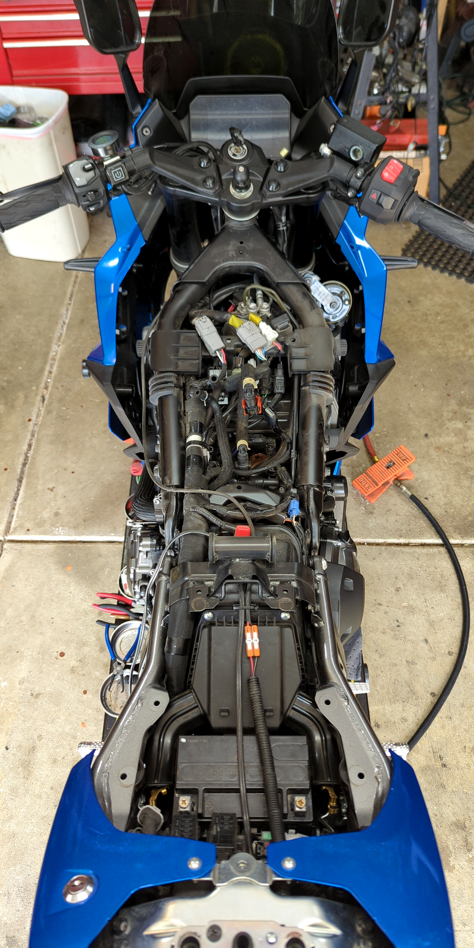
Assuming the tank is off and you're looking at a gallon-size bowl of electrical ramen, take a break.
Lower Plastics
For the fairing's under-plastics, meaning those which shadow the painted fairing parts, remove nine (9) push-pin connectors. There are six (6) on the inside by the wheel, though one was likely already removed for the tank cover pull. Same goes for the one (1) at the dash "flair" or "curtain".
Now, for the belly portion.
Look for two (2) big, screwdriver lift-type pin connectors at the belly pan. Slip the plastics front-to-back (rider perspective) back 'n' forth to loosen up the feel, then mind the individual slots connecting what's painted to their respective interior. Slip apart, disconnect the turn signals and we've got radiator access.
Wiring
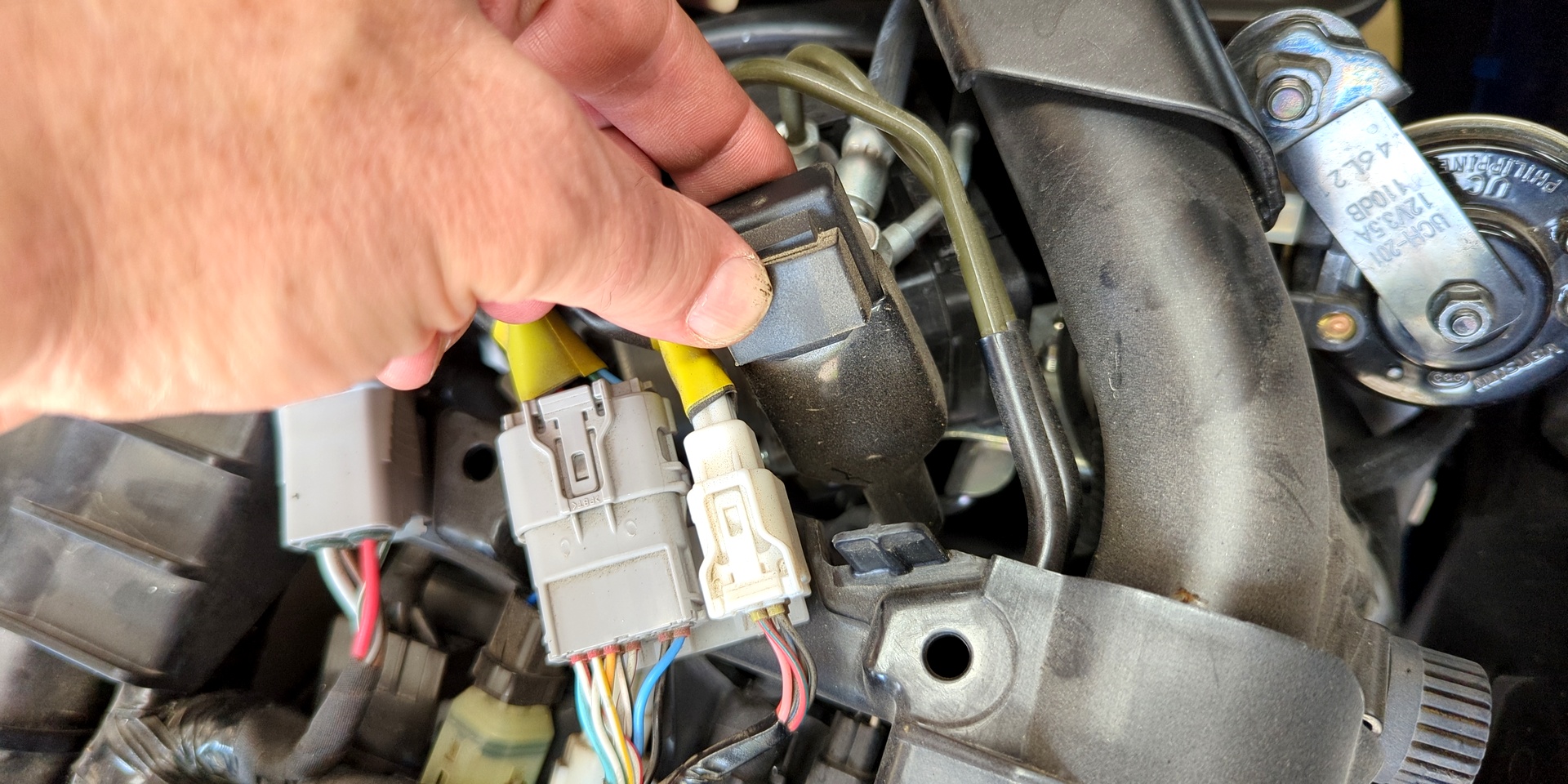
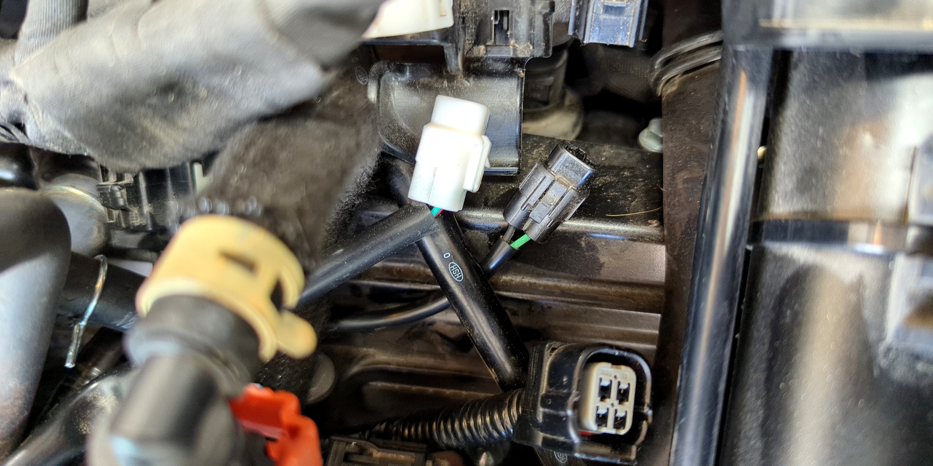
There are nine (9) total wire connections that need to be addressed. Eight are unique Molex variations that require disconnecting. The last is our LED blinker relay, which simply needs to be lifted from the "tooth" bracing its sheath.
All of the wires we're to disconnect are routed through or fastened to a plastic guide plate, which must also be removed. Because they're sorted over top of one another, let the following photos serve as a multi-angle path reference.
Use the left/right slideshow nav for visual steps ...
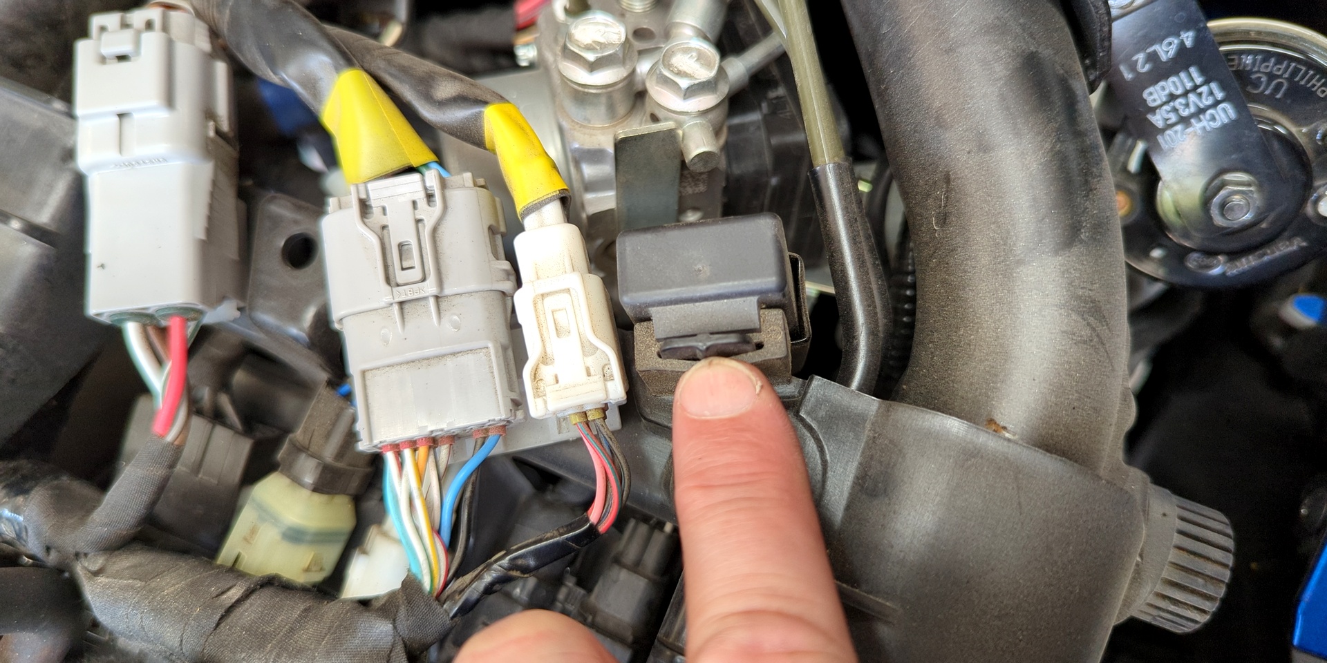
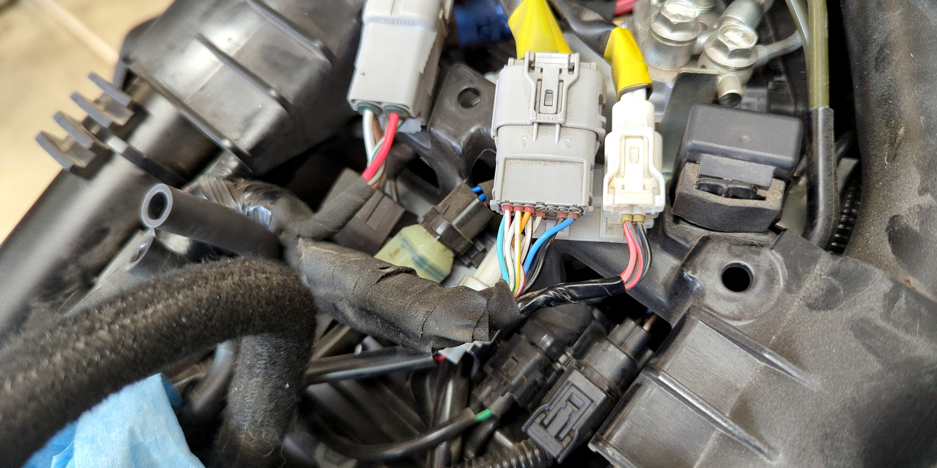
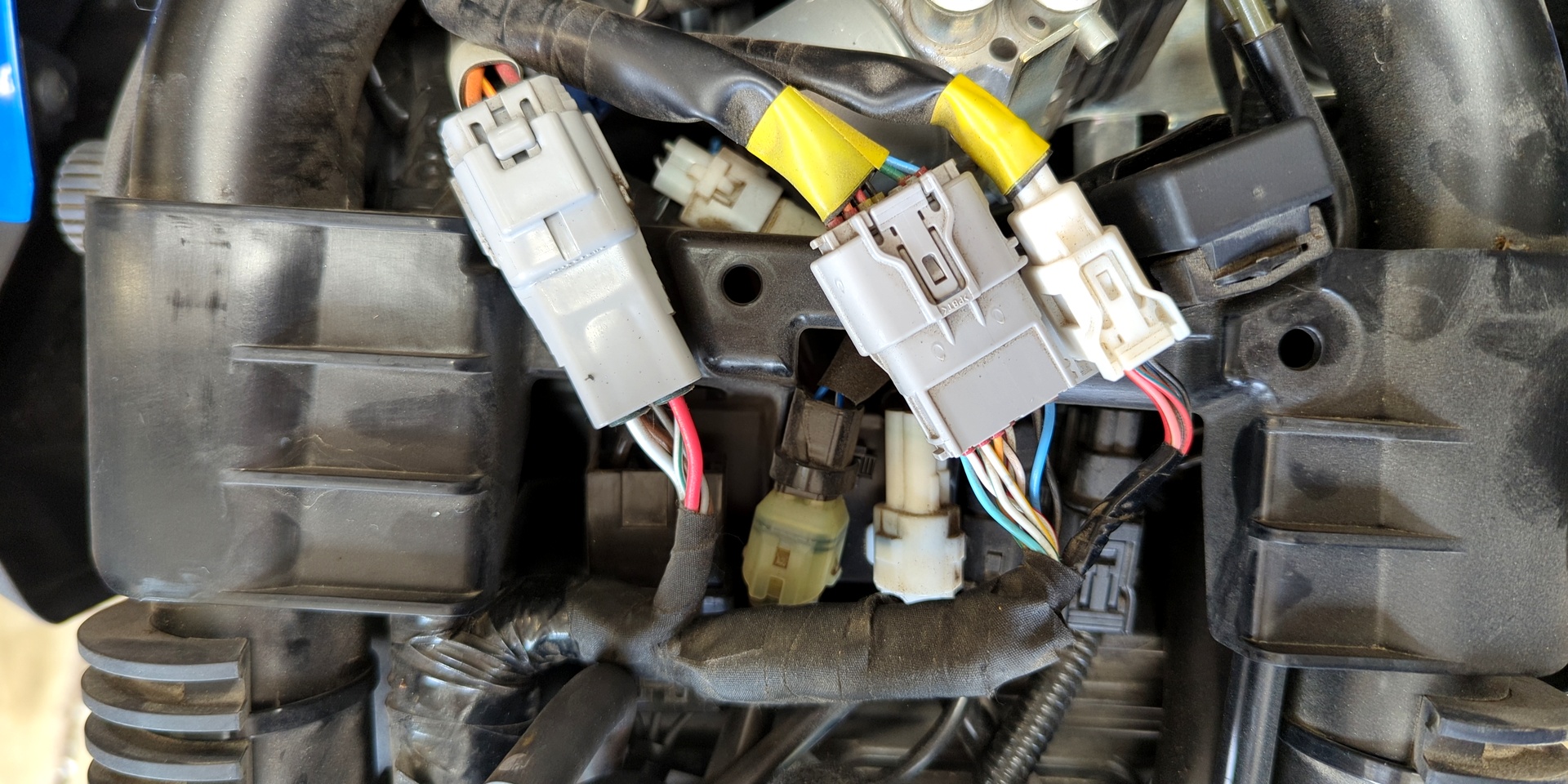
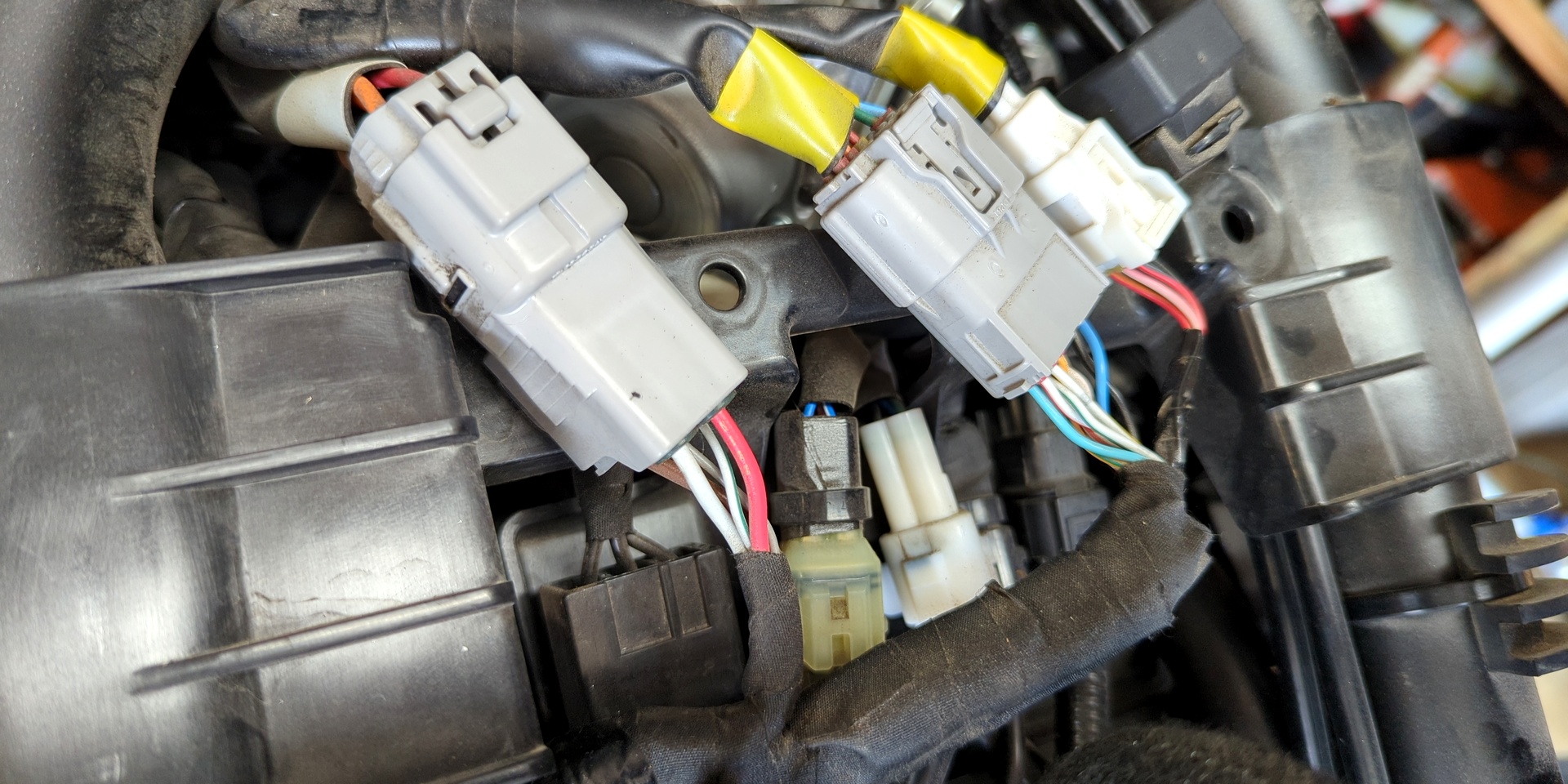
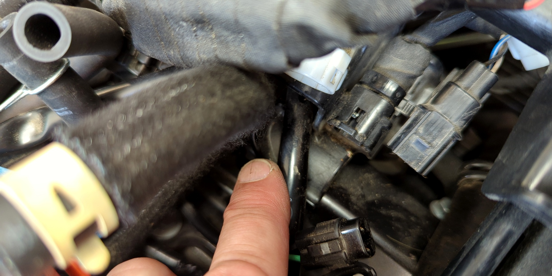
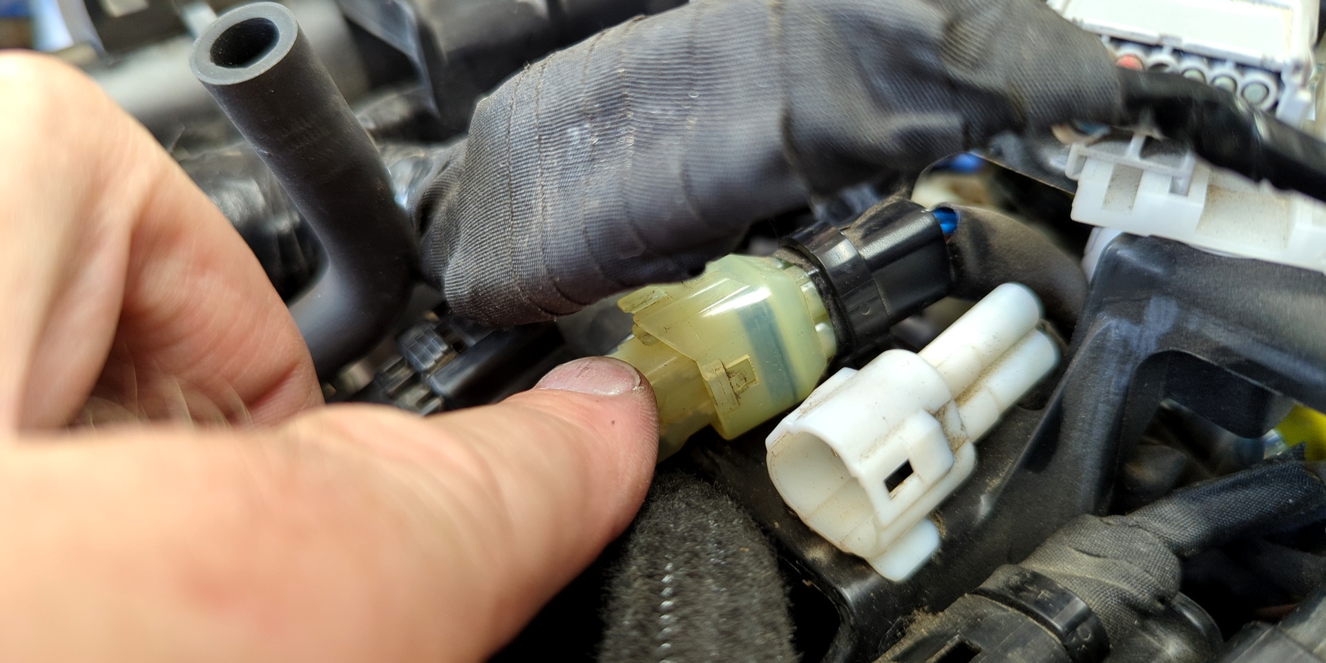
The bulk of the Molex connectors are tongue/tooth click-on. Most require raising the tongue with a small screwdriver before pulling free. There's a well-known trick to lifting each tongue and twisting the screwdriver so that it begins to slide away, but it takes practice.
Do note that:
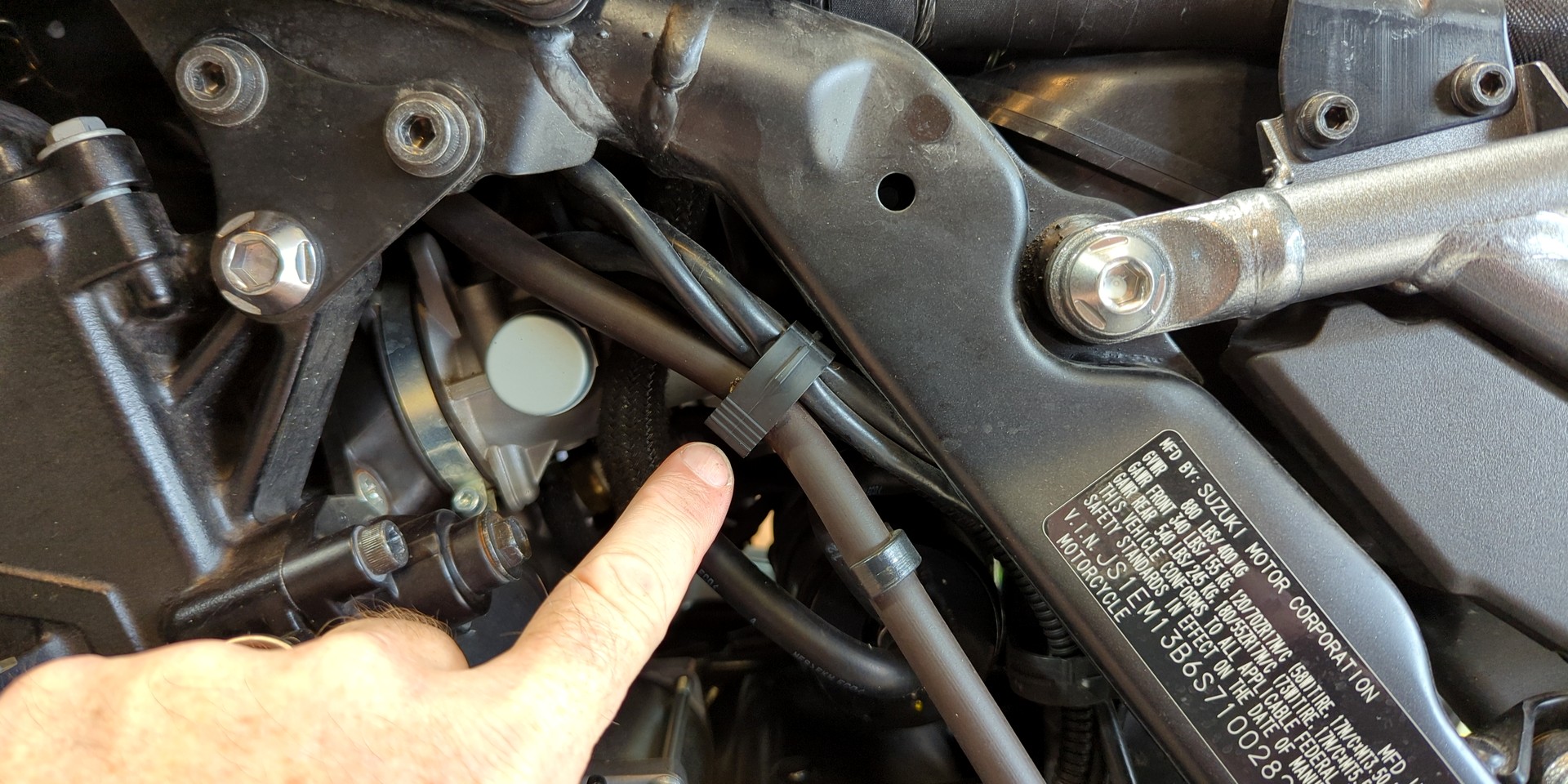
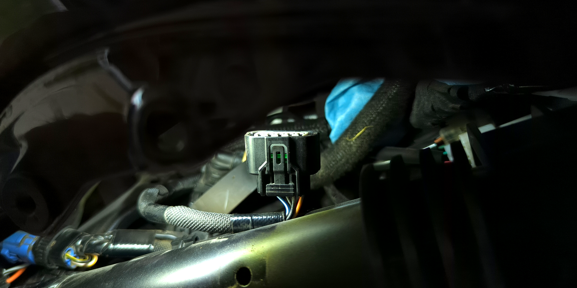
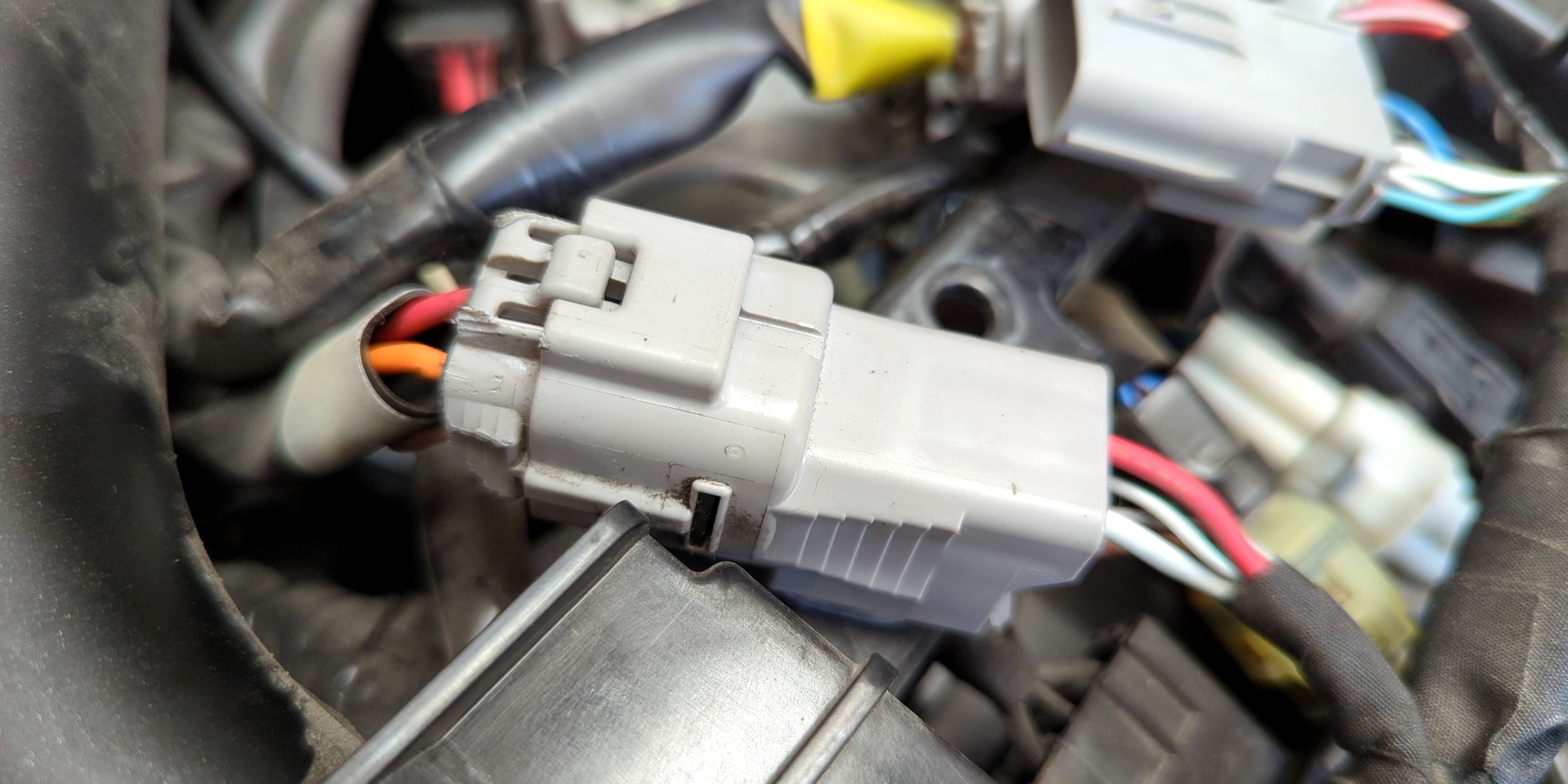
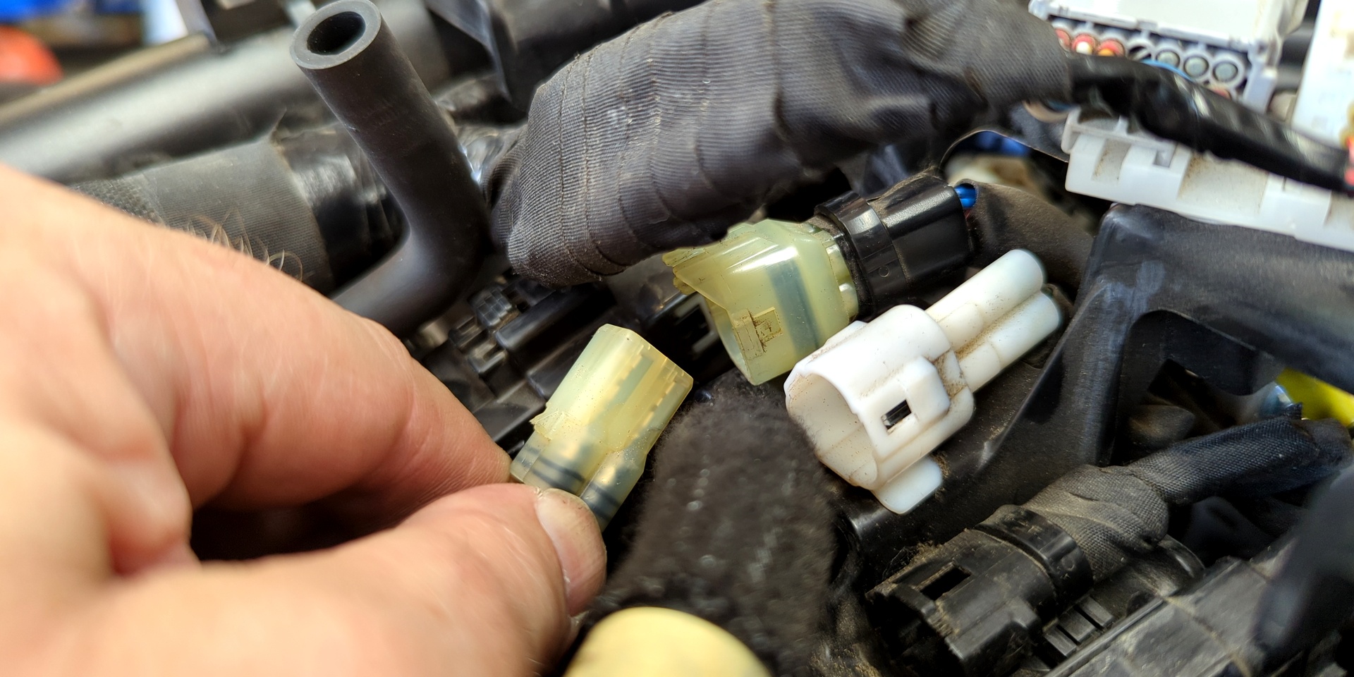
- The large front/top/left connector has squeeze-to-release "buttons"
- The small front/lower/left-of-center (white) Molex has a lift tab, not push/press
These are more difficult to separate, so tap into that patience we talked about. Unseat the large wire which is routed through a divot in the cross bracket. Remove the cross bracket plastic release pins (big, wonky push pins, use a flathead screwdriver).
Ignition Coils
Let's get to those spark plugs, shall we? Press down on each ignition coil wire connector tab (under tape, which can be left in place) to the furthest *forward* point (toward front of bike). You might hear a light "click", which is good. Then push the wire connector forward with a forgiving, screwdriver-shaped piece of lightweight plastic. The ignition coils have rubber seals. Just twist, then pull! There is no "line-up point".
Once all of these wire connectors are separated, carefully remove the guide plate from its location and set it aside with the other plastics. Get a few of those neon green zip ties before fastening the various wires and gas tank hoses to an adjacent left/right portion of the frame. The goal here is to keep them out of our way while we work, positioned as far back from the valve cover as is safely feasible.
Radiator
I have a habit of weighing true-to-form instructions against "sure would be nice if" non-solutions, such as the direction in which to feed a valve cover once its fasteners are removed. My Bandit 1200, Hawk GT, Street Triple R, R1200RS (actually, never mind that one) ... all the same. For every license plate hanging on my "sold" wall, there's a moment in memory where simply making eye contact with the valve cover begs the question "why can't we just yank it from this angle?"
Let's all take a moment to murmur this mantra together:
“The radiator must be removed so that we can feed the valve cover through the front of the frame.”
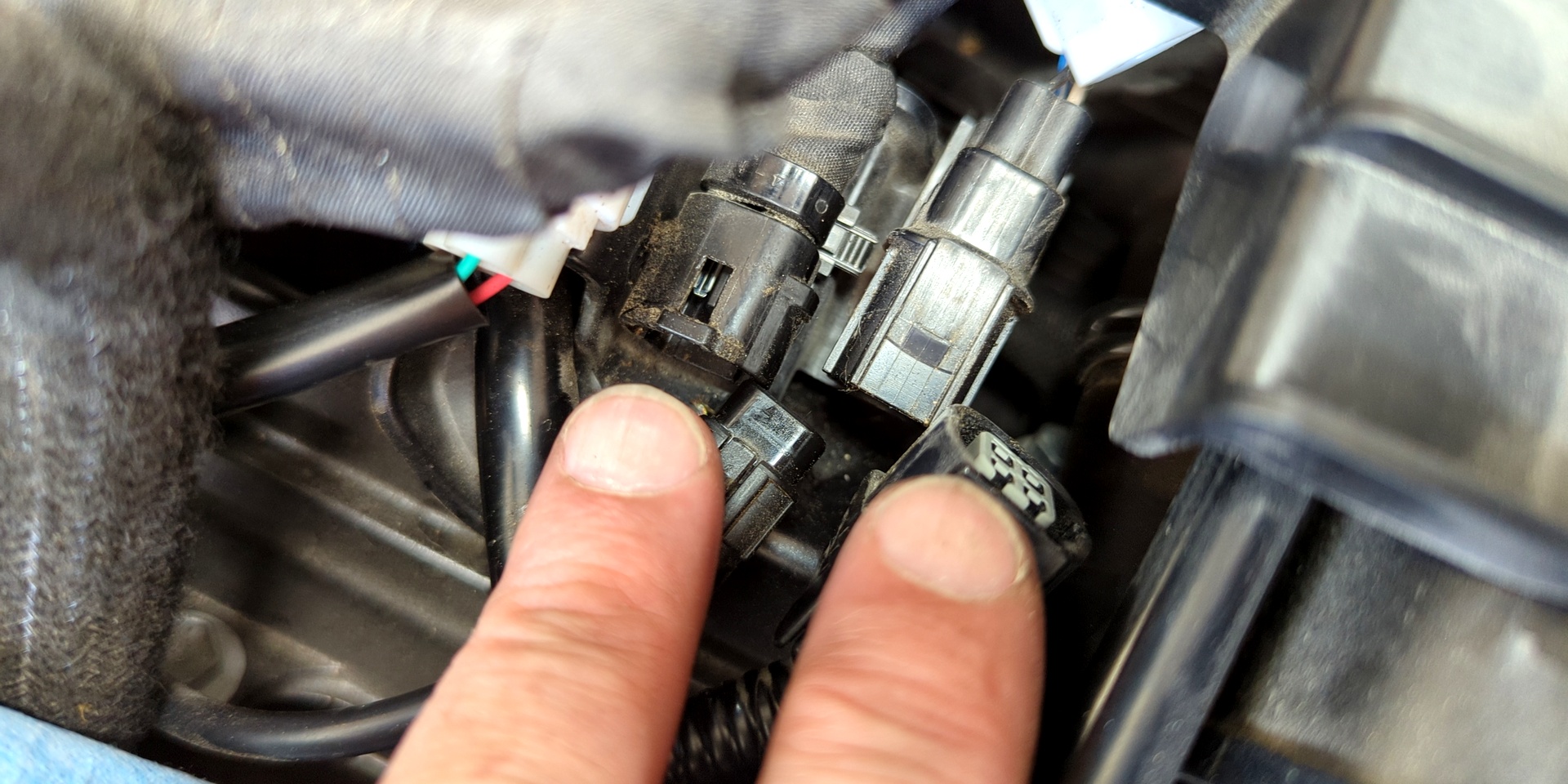
Outside of a few easy-to-spot nuts and bolts, there's little involved in removing the radiator. We're looking to pull two hose connections total: back/lower/left + back/lower/right of the radiator itself. Then, a large Molex connector must be separated. The male end is toward the rider while the female is embedded on the fan unit. Press the top of the male Molex connector to pull free.
The radiator is supported on two hook-shaped nodes which allow it to tip forward for easy lift-release.
A Pair Of Pairs
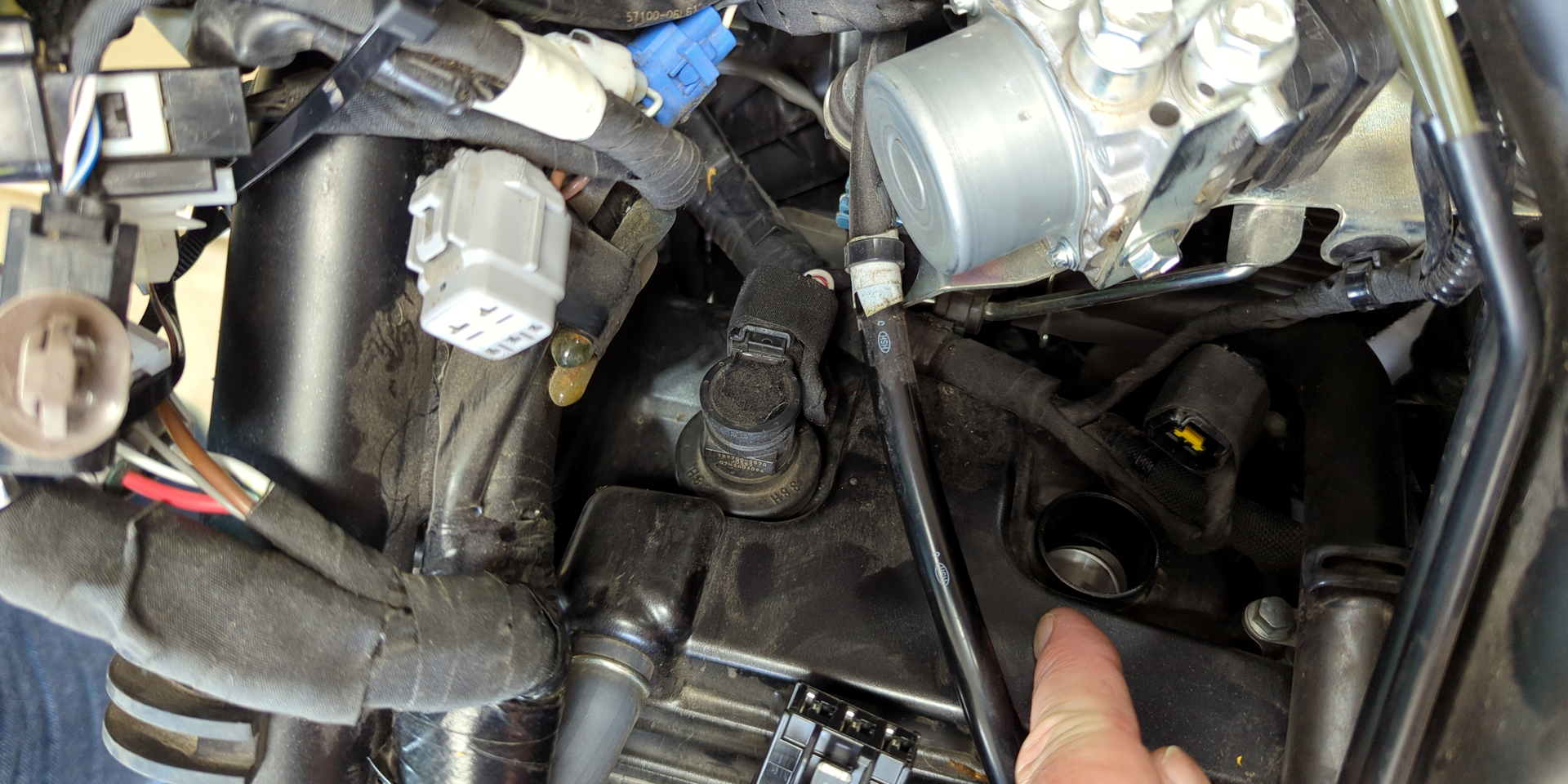
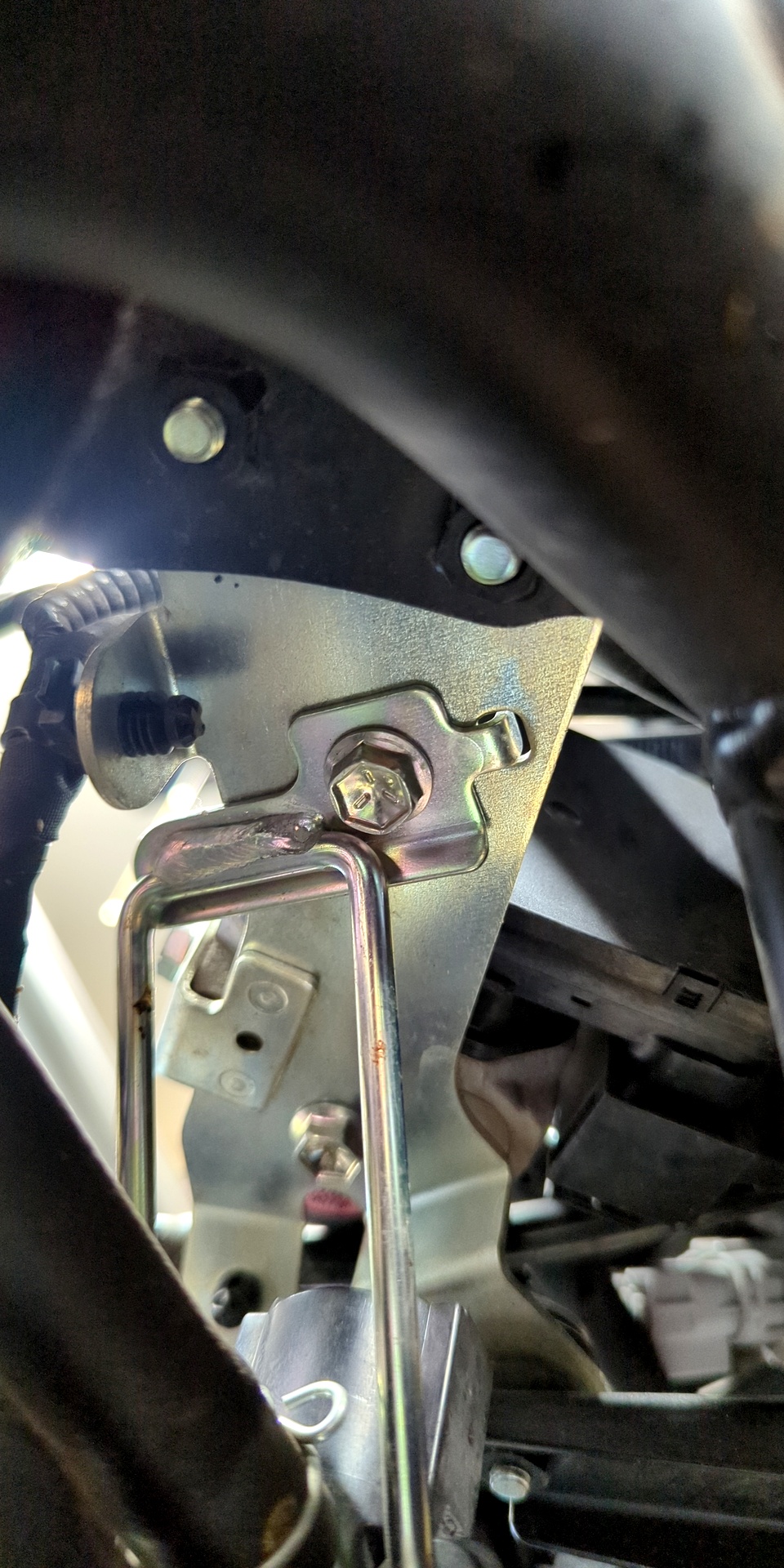
Behind the radiator are two more obstacles in the form of PAIR valves. Access to their wire mount comes with a bonus obstacle, the regulator. Removing the regulator is as simple as unfastening three bolts, then letting it hang freely for the remainder of the valve service effort.
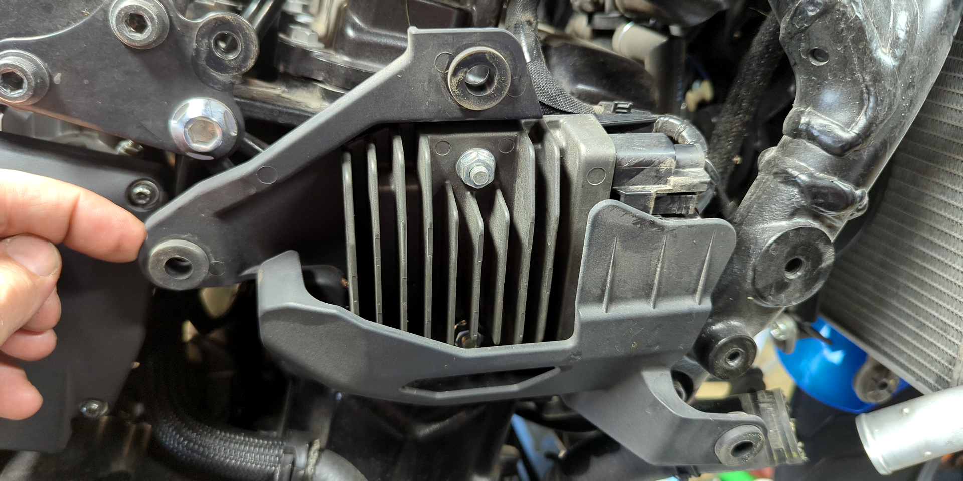
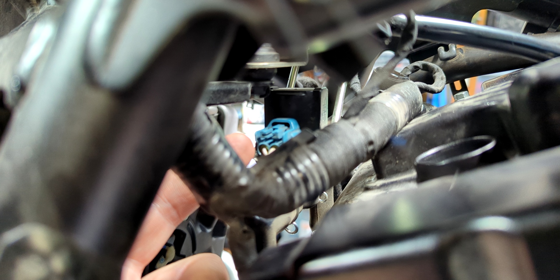
To un-situate the PAIR system, first look for a blue Molex connector on the left-hand side of the bike toward the rear of the valve cover. Pinch it from the top and slide left(?) to disconnect. Remove the 10 mm bolt from underneath the metal dowel mount, then shift it enough to slide the entire PAIR system off.
Use the left/right slideshow nav for visual steps ...
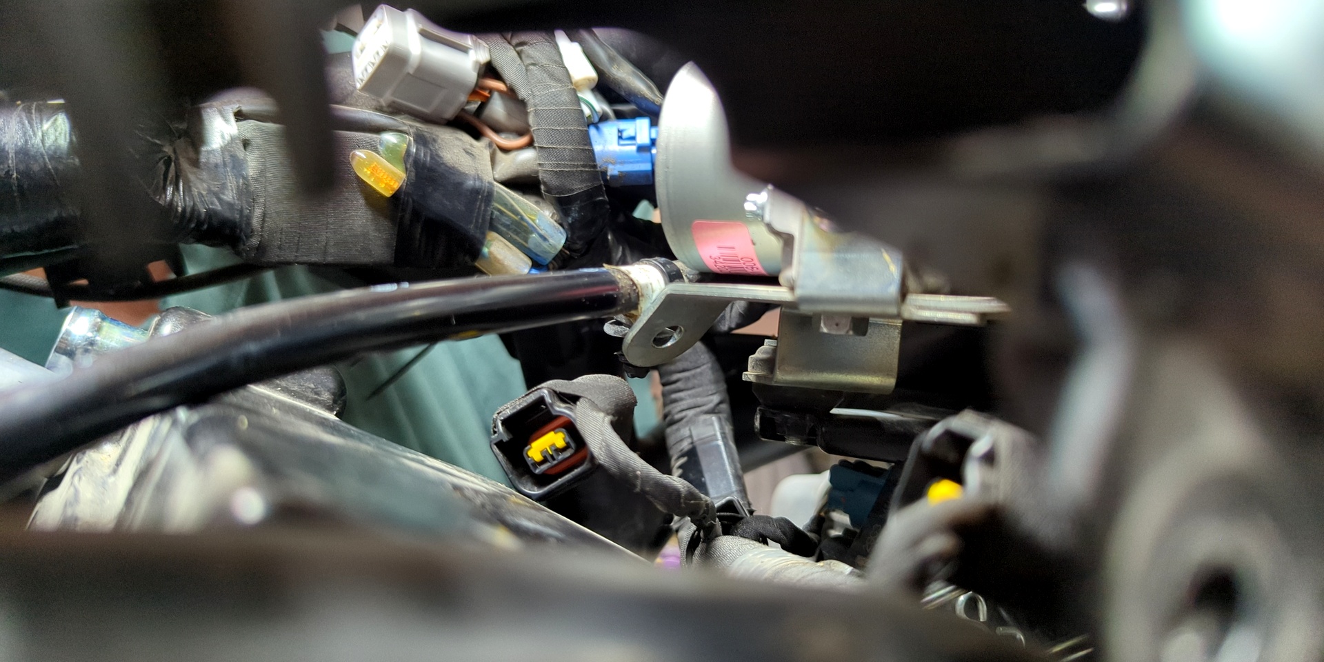
Disconnect both PAIR hoses from the engine. One is in plain view to the rear/left of the valve cover. The other is at the intake port of the PAIR control solenoid. At this point, the dowel mount should be clear of any remaining items. Pull it entirely and set aside.
GSX-8R Valve Check: Finally, The Actual Process!
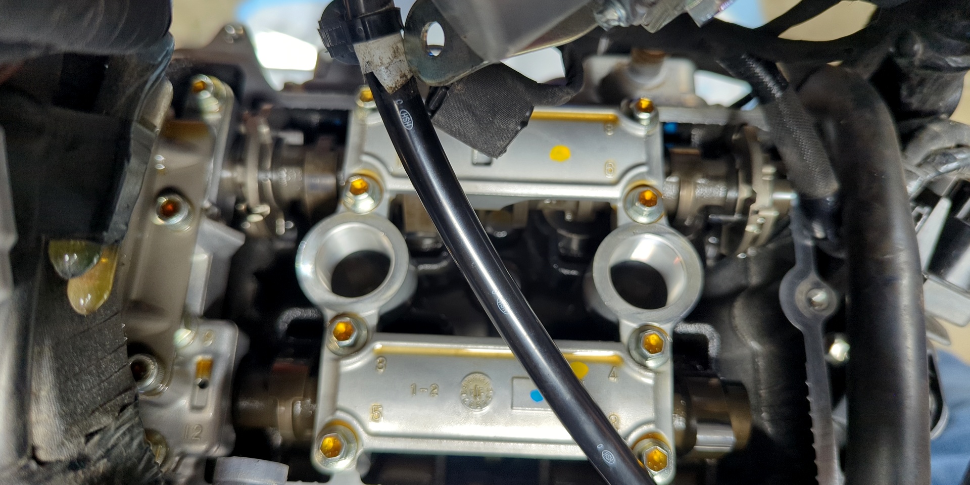
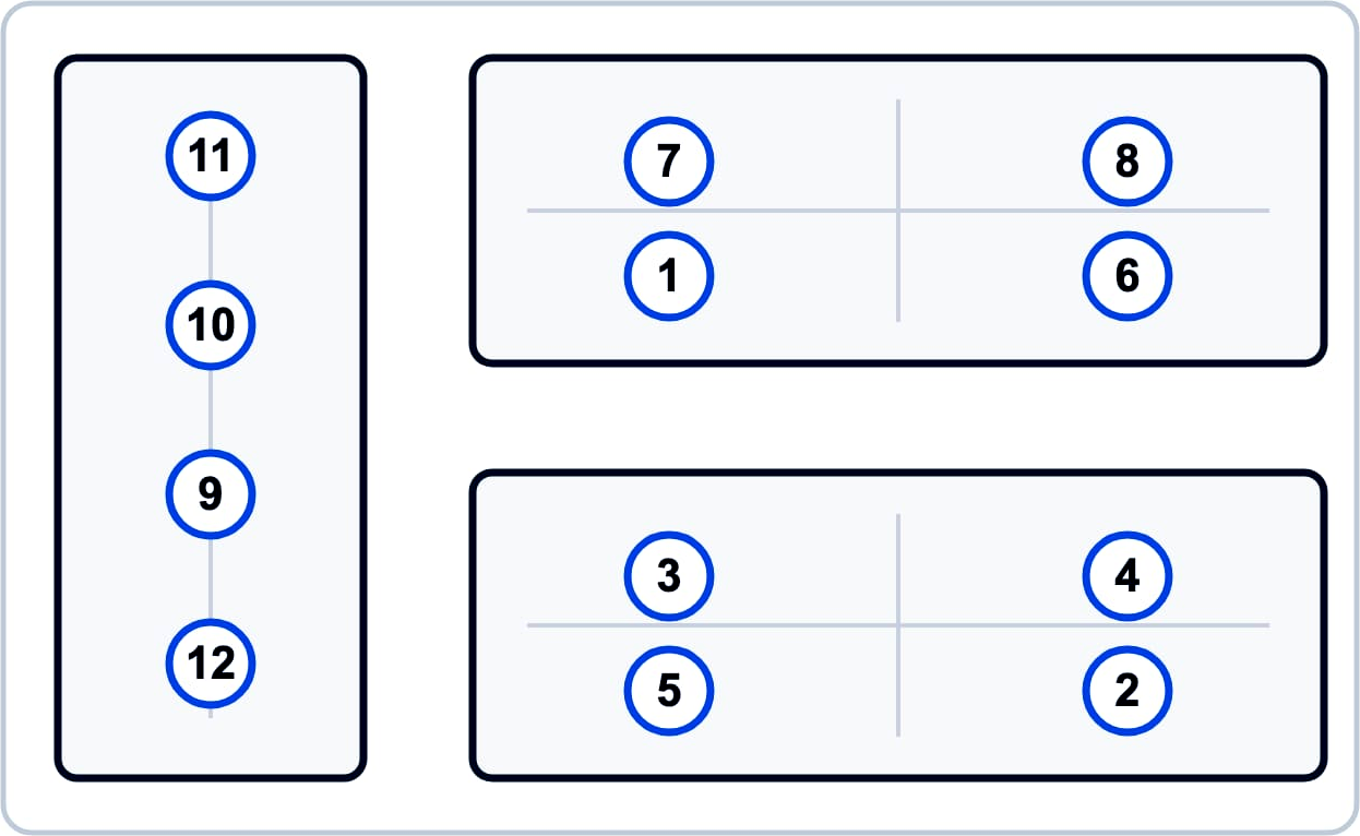
To remove the valve cover, loosen all eight (8) of its overhead screws and set them aside. If you want to reverse Suzuki's tightening instructions, look at the bottom right-hand corner of page 1D-15 in the factory service manual. If turning the pages of that structural liability of a granite slab isn't appealing, the loosening pattern is (from rider perspective) ...
- rear-center
- front-center
- left
- right
- front-left
- rear-right
- rear-left
- front-right
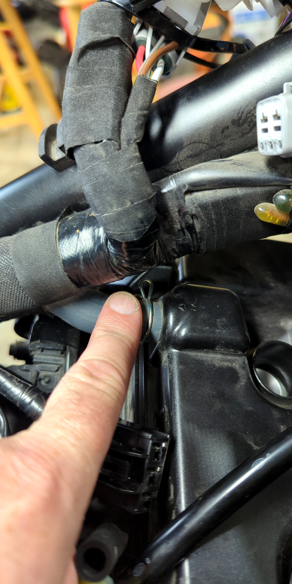
Remove the flexible hose guide from the right (for clearance) and free the clutch cable from its guide brace, which is a plastic vehicle connector of the finned "Christmas tree" variety.
By the time I got the valve cover off myself, stress was running high. It's at this point we gotta remind ourselves ... we're 90% done! Yes, there's also reassembly but to quote any Haynes or Clymer manual: "reassembly is much the reverse of disassembly" (eye roll).
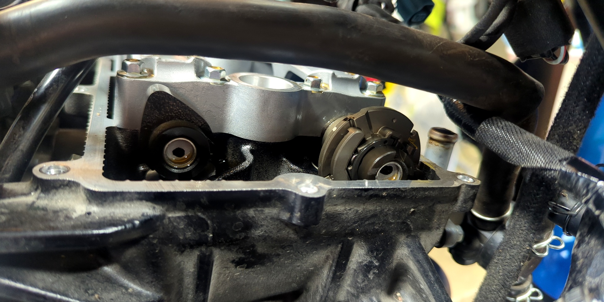
TDC Access
The main thing to do before measuring GSX-8R valve check tolerance is to find TDC (top dead center). Only after the cam lobes are in the correct heel position can lash clearance between the tappet shims and camshafts be measured. For clarity, these next two instructions assume you're viewing the left side of the engine while directly facing the left side of the bike.
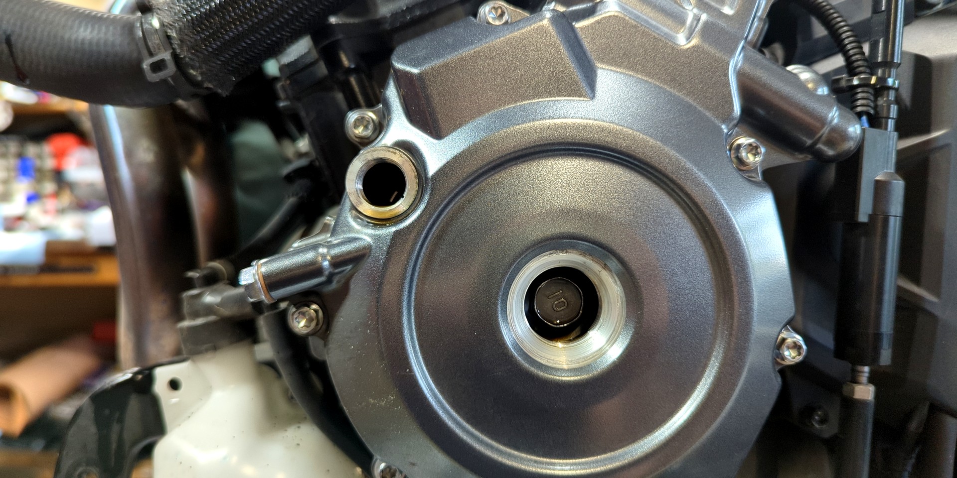
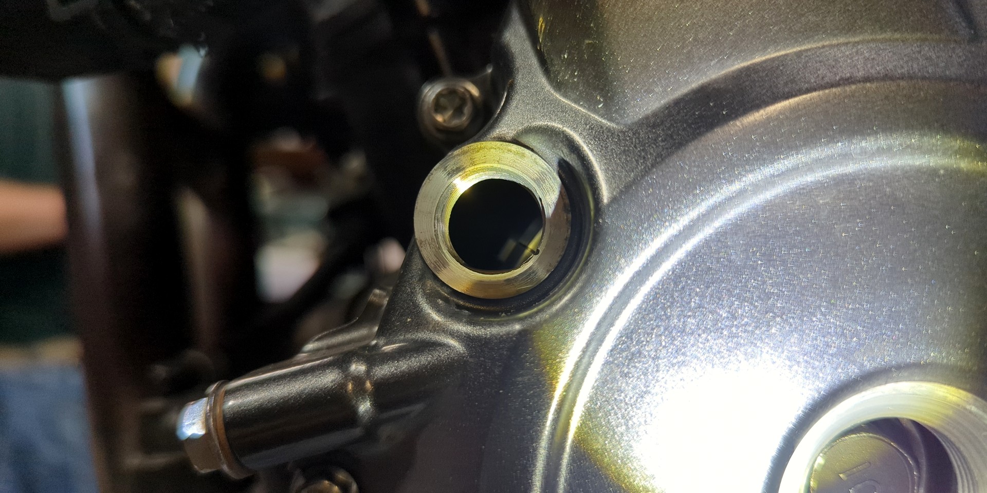
To find TDC, access the large black bolt behind the small(er) center outlet in the middle of the magneto cover. Then, remove the small viewport cover from the top left of the magneto cover. Turn the crankshaft bolt counterclockwise (crucial to avoid putting unwanted stress on the valve train) using a solid T-handle (not a ratchet) and 17 mm deep-well socket.
Crank until the thin TDC line appears inside the viewport, aligned precisely with a tiny notch in the cover outlet's threads. The notch might appear to you as a manufacturing "mistake" at around the 4:00 position. Cylinder two is marked by a "II", with no notch (use the space between).
Use the left/right slideshow nav for visual steps ...
Measuring & Adjusting Tolerance
Maybe you prefer go/no-go feeler gauges over basic. I've been on both sides of that argument, so follow your heart. Because we want to run the feeler gauges center-to-outside, basic feelers may prove easier to work with.
Intake: 0.10 ~ 0.20 mm
Exhaust: 0.20 ~ 0.30 mm
For you inch weirdos, that's 0.004 ~ 0.008 inches intake, 0.008 ~ 0.012 inches exhaust.
Valve clearances always get tighter, both through wearing of the valve material at the "lip" and changes in shape from the hammering of millions of cycles. Exhaust valves wear and change clearance somewhat faster than intakes due to the extreme heat. As a general rule, valve seats are much harder than valves and do not measurably wear.
The clearance for exhaust valves is most crucial because of the "dwell time" needed sitting on the valve seat where the valve can transfer heat to the cylinder head. If it ever gets to (or near) zero clearance, exhaust gases will quickly overheat the exhaust valve and begin to cut trenches into the valve like a cutting torch.
For this reason, we want to measure everything first, documenting our feeler gauge findings along the way. If everything is between the middle and top of spec, meaning higher clearance, we're better than good. Once even one measurement finds its way toward the lower digits, it's time to pull the cams.
Below are the measurements I found on my own steed. Click the image to open a clearer, easy-to-read chart.
This is precisely why it's wise to check and document the results for every valve in an easy-to-reference way. Despite everything being technically within spec, it's clear that my exhaust valves could use some love. All of them are on the low end, 1R being at the bottom limit. At TDC, we want the distance between the base of the cam lobe and the pot covering the shim to be as close to the top end of spec as possible (without exceeding it). The GSX-8R valve check math goes something like this ...
And of course, wouldn't ya know it, my constant disrespect for the rev range both along the twisties and the track lands me in some worry-worthy math, sssooo ...
Damn, Cam!
Big thanks to Brian for our Zoom meeting revisit to clarify all matters muddied. Yes, off come the cams. Before they do, however, we want to protect the engine's timing.
- Crank everything to TDC again
- Remove the cam chain guide/cage
- Remove the cam chain tensioner: 1 bolt to loosen spring load, chain goes slack, 2 more bolts to unmount
Next, the cam guide assembly is a giant aluminum single-cast piece that spans the entire engine left-to-right. It's held in place by eight (8) bolts total. Next to it (left of rider position) is the cam gear assembly cover, which has a total of six (6) bolts, four of which lock the cams into position and two of which allow cover and guide removal.
Right about now, ya might wanna take a side-angle photo of the cam arrow timing positions for good measure. Maybe you'll need it. Maybe you won't.
Per the service manual instructions, there is a pattern to the bolt loosening order. You can find this information on page 1D-18 but in descending numeric order, it's as follows ...
We also have to be careful removing this component as it's held in place by four metallic dowels that, while resistant to motion, are begging to drop into the engine. Don't let it happen. Address them before moving any further, else the GSX-8R valve check will come to an unwanted intermission.
At this point, the cams are freely removable but only remove one, so that the chain doesn't drop. Use zip tie(s) to secure the chain before removing the second cam. It's not about timing (yet). It's about maintaining parts access. While it's not a disaster if it should fall, this article doesn't cover that recovery process, so good luck!
You now have bucket access! Use a handheld magnet to pop one out. The shim will either be stuck to the valve - or - not there? Oh no! Relax and look into the bucket (no biggie). Docu-write its exact size and bucket location in the engine. Measurement is written on the shim itself.
Before you swap out the old shim for a new "surely it's the correct size" replacement, measure the new shim with a micrometer just to be sure. It might be wrong (it does happen). If all is well, place a tiny droplet of oil onto the shim before positioning it, place the bucket back over top of it and move on to the next.
For whatever reason, the manual tells us to install the shim with the numeric measurement facing downward.
All done? Onto the timing markers. Let's keep this part short and to the point. You bought the manual. You keep track. We're not going to explain the timing here. Follow the instructions on page 1D-20 to the letter.
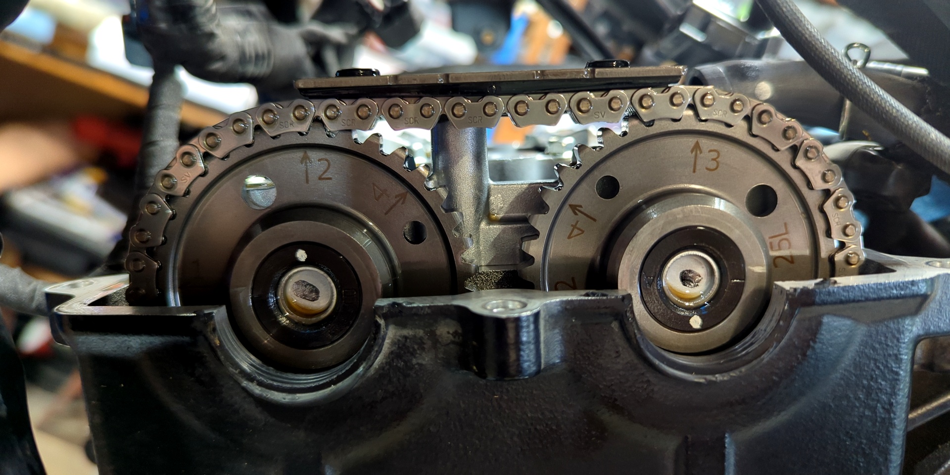
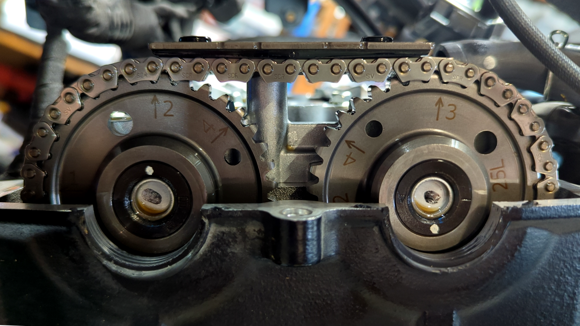
The sloppy version is this: At TDC, viewed from the left side of the engine, the #2 arrow on the exhaust camshaft gear and the #3 arrow on the intake camshaft gear should be pointing as close to "up" as possible while dividing 14 pins from the chain between them. See this image. #2 points directly at the first of fourteen chain link pins and #3 points directly at the fourteenth pin (count 'em yourself).
As for cam re-installation, the front (exhaust) goes in first, then under the chain (taut but no yankin'). Install it to match the markings per the manual. You'll be counting chain link pins based on the manual timing points. The pin count is everything and there's no harm in marking them up with a paint pen, nail polish, whatever helps. Mark the intake side with this.
Now, carefully mind the dowels and everything else. Get all of the retaining plates, dowel pins and bolts back into their designated locations and keep it all loose. Before the retainers get tightened, slide zip ties through the holes in the cogs/sprockets/whatever Brian insists on calling 'em and around the chain, tightened, so they won't skip.
The cams are under tension from the valve springs. That means they can rotate while the retainers are being fastened. To thwart this, we lock the chain to the sprockets for a few minutes.
Even with the safeguards that Brian and I put in place, we kept completely silent during the cam reassembly effort. The slightest misalignment in the timing can cause a terrible running machine or worse, a two-wheeled brick of a paperweight. When the quietest "shick!" sound made its way through the garage, I turned and looked at my friend, who was holding as still as possible, before looking up and asking "you heard that too, right?"
The cam chain can slip, folks. More accurately, the cams can try to rotate under valve-spring pressure while the retainers are being tightened. If the chain isn't locked to the sprockets, that tiny movement can become a timing hop.
The sequence matters. Get the timing right, count the pins, confirm the arrows, zip-tie the chain to the sprockets, tighten the retainers, install the cam chain tensioner and only then remove the zip ties. Silence is nice but zip ties are what keep the garage from learning new vocabulary.
Double-check everything, then tighten each bolt according to the manual (page 1D-21), this time in ascending numeric order. Do know that the cams will move a little while doing so and that's okay. Just follow the sequence and leave the zip ties in place while the big/small retainers are tightened.
Once the cams are locked down, install the cam chain tensioner with the zip ties still in place. All things plunger and body are explained on page 1D-22 in the manual. With the retainers tightened and the tensioner installed, the chain should no longer have the freedom to do any party tricks.
Now remove the zip ties and rotate the engine twice, watching over the process to confirm it arrives back at an identical cam/sprocket position. You'll hear some noise. That's the cam chain tensioner finding its way back to taut.
If everything lands where it should, reinstall the cam chain guide/cage before the valve cover goes back on.
Buttoning Up: Engine, Cooler, Wiring, Plastics
Follow all engine-related bolt and fastener torque specs to the letter, using appropriate accuracy tools, per the service manual. That applies to the magneto and viewport outlets as well. One noble predecessor to this write-up mentioned shearing the magneto cover access port threads (where we crank to find TDC). It's safe to assume anything assigned a torque value below 20 ft-lb should be given that "less is more" mechanic's feel. If you strip the TDC plug, you need to get a new magneto cover and a new clutch sub-assembly because you cannot pull those bearings out in a non-destructive way.
The Cooling System
Once the radiator is back in place and the hoses connected, refill the system with the correct coolant and burp it like any other liquid-cooled motorcycle. Air pockets aren't decorative. They interrupt coolant flow, confuse heat transfer and do their best impression of overheating.
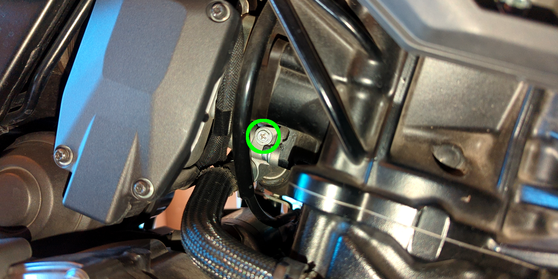
Suzuki adds one extra "oh, there it is" moment. It's a cooling system bleed point that needs attention, not just the usual radiator-cap-off squeeze-and-rock routine. Open the bleeder using a Phillips or socket, let trapped air escape until coolant presents itself cleanly, then close it back up before topping off the radiator and reservoir to spec.
Also, for the love of all things aluminum, be kind to the radiator hose outlets. If the OEM spring clamps have been chewing at your patience or the hose connection looks even slightly ovated, replace them with proper screw-type clamps and sleep better. Run the bike through a heat cycle, watch for leaks, confirm coolant level once it cools and only then call the cooling system done.
"Everything Else" Reassembly
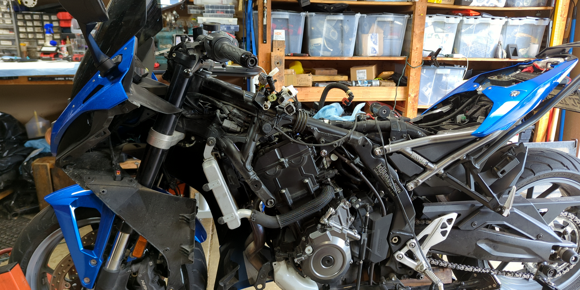
There's plenty of truth to Haynes/Clymer's mention of reassembly being a simple reversal. Problem is, they never offer enough visual reference to understand what Jengas to which Tetris. Hopefully the images in this article will prove useful for your first-gen 8R.
This being a GSX-8 series valve check and with new model variations hitting the market that make use of the same engine, it's best you take lots of photos of your effort along the way. Having taken the above photos myself, even I woke up the following morning realizing I needed to go back in to reroute a misdirected wire through the plastic guide plate. There's no reason to try and convince ourselves we won't forget when smartphone tech is always within arm's reach.
If you have the 8R or a drive full of your own pics on hand, slowly investigate the details and retrace your steps. Even the connection points you have to feel around for in the blind will arrive at "yup, done" status. Stay patient and your bike will be back on the road in no time.
Suzuki GSX-8R Valve Check Summary
The GSX-8R valve check isn't mechanically scary so much as spatially annoying. The 776 cc parallel twin is friendly enough once exposed but getting there means plastics, fuel tank, wiring guide, radiator, PAIR system and valve cover all wanting to remain tangled. Buy the manual, bookmark the relevant pages, gather every seal, gasket, o-ring, shim, spark plug and coolant item from dem dare lists before the bike comes apart and give yourself more time than your ego says is necessary.
The actual measuring process is straightforward: cold engine, TDC, feeler gauges and careful documentation. If everything lands in the upper half of spec (0.10 to 0.20 mm intake, 0.20 to 0.30 mm exhaust), congratulations, you get to reassemble without summoning the camshaft goblin. If the numbers are tight, especially on the exhaust side, cams come out, shim math comes in and your new best friends are zip ties, photos, paint marks and the Suzuki manual's timing instructions.
Reassembly is where patience pays rent. Replace the required o-rings and seals, torque engine fasteners exactly, treat the magneto access plug like it's made of compressed lawsuit and be gentle with the radiator's soft aluminum hose outlets. Refill and bleed the cooling system, heat-cycle the bike, check for leaks, verify coolant level once cold and review every connector, hose and routed wire against your own photos.
Do all of that calmly and the GSX-8R goes from exploded laptop ramen back to a road-ready motorcycle!
Is The GSX-8R Valve Check A Right Of Passage?
Motorcycles are becoming both more and less complicated. What modern tools have you acquired to answer the call? Which ones do you prefer most and why? Your input is invited. Leave a comment and/or write an article!
Share Link ...

About Robin Dean
Motorcycle advocate, enthusiast and traveler. Founder, The Riding Obsession (2014). MSF RiderCoach credentials: "loosely regarded adult supervisor, probably good enough for rock 'n' roll" ~ Tidal Playlist | Rabid Neon

Thoughts gone wild? Write an article!