Unfold our FTC disclosure melodrama here. The following article was last updated on Oct 19, 2025 ...
B12 Valve Inspection And Adjustment
Adjusting the valves on a 2nd generation (2001-2005) Suzuki Bandit 1200 is time-consuming and sometimes frustrating because the service manual does a poor job of explaining the Suzuki Bandit 1200 valve adjustment process. Set aside several hours because it involves removing the seat, tank, front bodywork, some items under the tank, spark plugs, head cover and signal generator cover. Also, the engine must be stone cold for at least 12 hours.
“Follow this step-by-step guide for a complete Suzuki Bandit 1200 valve adjustment, including tools, torque specs and setup tips.”
There are some tricks to adjusting forked rockers and some omissions in the techniques in the shop manual. I highly recommend buying the $5 US tool #09917-14920 valve adjuster driver, a small tool that mates with the tiny square head of the screw adjusters and is extremely useful in holding the screw while you tighten the locknut. If you don't have it, you'll have a hard time maintaining the proper lash as you tighten.
Gaskets and Washers:
Of the following, only the signal generator gasket demands replacing and even then, many have gotten away with not doing so. Each rubber gasket is reusable so long as it remains spongy/pliable. Inspect the four metallic washer gaskets accordingly. In short, order any of the following that you don't already have. When you need a new gasket (and eventually you will), keep its replacement with you and order another upon installation.
Gasket, Signal Generator Cover (x1)
Gasket, Cylinder (x1)
Gasket, Head Cover (x2)
Gasket, Head Cover (x2)
Gasket, Head Cover (x4)
Washer (x8)
Tools and Chems:
US Tool #09917-14920
Feeler Gauges (x2)
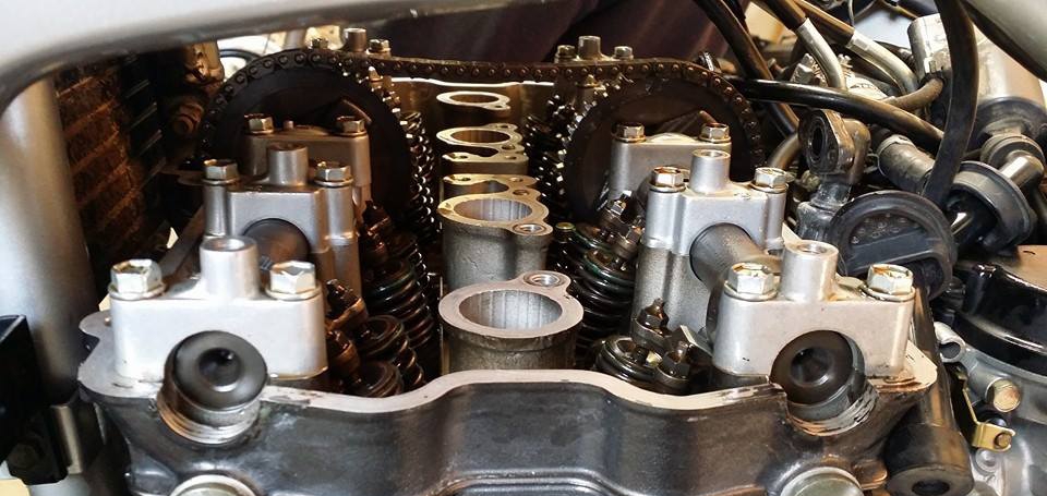
Permatex Blue or Ultra Blue
Gasgacinch (optional)
Torque Wrench
Ready the Bike:
Much of what you're about to read with regards to bike prep applies strictly to the faired "S" type Suzuki Bandit 1200 valve adjustment process. However, plenty of the instructions are universal to faired and naked versions alike. We leave it up to you to decipher what's what with regard to plastics versus otherwise.
1) Remove the seat.
2) Remove the gas tank by unscrewing/removing the petcock knob and two securing bolts toward the seat latch before then disconnecting the fuel/vacuum hoses on the left side and fuel level meter + breather/overflow hoses on the right side.
3) Remove both mirrors by rolling back their elastic covers and unscrewing their two Allen bolts.
4) Remove the "V"-shaped upper plastic from the front fairing by removing the two Phillips screws (toward the top of the dash) and two Allen head shoulder bolts on front before pulling diagonally forward/downward, "popping" it out of the fastener insert.
5) Remove the windshield by removing the two screws at its left and right base before flexing outward from the top and lifting away.
6) Remove the plastic "chin curtain" from the lower/center fairing by first compressing the four push-pin connector buttons and removing the push pins. Next, unscrew and remove the two (upward-pointing) Allen head shoulder bolts.
7) Disconnect the turn signals. If the wires are seemingly inaccessible, disconnect one side of the fairing first (#8) and suspend it in one hand while accessing the wire connection with the other.
8) Remove the left fairing by removing the two large and two small Allen head shoulder bolts located (from side perspective) at the top right, middle right, center base and top left. Much like the "V"-shaped upper plastic from the front fairing, carefully pop this part out to the direct left of rider position (not diagonally).
9) Remove the right fairing using a mirror-image process that's identical to step #8.
10) Remove the ignition coils, noting the position, routing and connections of the wires. A few shots from a digital camera will likely prove useful.
11) Remove the left/right fairing mounting braces from the frame just above the head cover.
12) Disconnect the breather hose as well as the breather cover (four bolts), making sure to treat the thin metallic gasket underneath with care.
13) Disconnect and remove the spark plugs before lightly packing shop rags into their respective tunnels. This helps ensure that engine bits don't fall into the combustion chambers.
14) Disconnect the oil head cooler hoses from the head cover by loosening their Allen head bolts.
15) Prepare to remove the head cover by removing the ten Allen head shoulder bolts in a crisscross "X" pattern. Their yin-yang position at the front/center-left and back right/center-right seemingly hides two of these screws. Next, remove the four hex bolts using an outward-to-inward pattern. Be sure not to lose the small metal gaskets under each of these bolts!
16) Gently lift the head cover and feed it from left to right. If it's stubborn to lift, use a cloth and a wide flathead screwdriver to gently twist it open. Look underneath as you guide the plug towers over the timing chain. You can easily lose one of the small gaskets at the base of these towers. Also note the two removable "keys" that keep the head cover and its gasket properly aligned. You'll find them at the front/left and rear/right corners of the head itself. Be sure not to lose either, as each might either remain in place or lift away with the head cover.
17) Remove and clean the head cover gasket (strip off any remaining silicone sealer) and the mating surfaces on the head cover. You can reuse this gasket as long as it's pliable.
18) Remove the right-side generator cover (so that you can crank the engine into adjustment positions) by removing its five Allen head bolts. If you're careful in peeling the gasket off, you'll be able to reuse it (once) with a Permatex silicone gasket maker (Blue or Ultra Blue) coating.
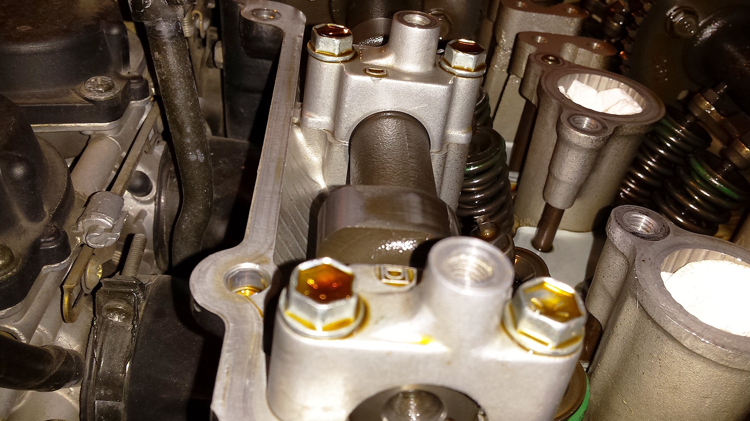
Note the two notches on the right ends of the camshafts for alignment. Rotate the crank to the two valve-adjustment positions so these align parallel with the head surface. Much like with any motorcycle, these markings don't always line everything up as exactly as one might hope. Once positioned, it's best practice to observe the cams until they point away from the valve before rolling them to their loosest point. In short, use the markers as intended before pointing the lobes 180 degrees opposite the rocker pad for each valve pair ...
Rotate the crank forward (clockwise) with a breaker bar or large wrench (19 mm) on the signal generator nut (right end of crank under removed cover) until the cam marks line up with the head surface (horizontally) on the outside of each cam (the marks will be "pointing" away from each other). In this crank position, you can adjust the intake valves (0.004 - 0.006") for cylinders #1 and #3 and the exhaust valves (0.007 - 0.009") for cylinders #1 and #2. Let's begin the Suzuki Bandit 1200 valve adjustment!
Suzuki Bandit 1200 Valve Adjustment Procedure:
Check the existing lash on each side of a rocker with one feeler gauge. If the two sides of one rocker differ from each other by 0.001" or more, or if either is out of spec, you must adjust one or both valves on that rocker.
“Once the engine breaks in, the valves on these bikes tend to remain stable. Many people never check them but that's not advisable. My 1100E is within tolerance every time I check valves. I often tweak them a little as I prefer consistency. My method is to pick a desired tolerance (.004" for the GS) and use a 'go/no go' approach via three gauges: .003", .004" and .005". The .003" should be 'go' and loose. .004" should also be 'go' but snug, roughly the same tension as pulling a strip of Scotch tape loose. .005" shouldn't go under reasonable pressure.”- Joe Nardy
To adjust, loosen the locknut and adjust the screw with the $5 driver you bought until the desired lash is there. Tighten the locknut gently as you hold the screw with the driver. Repeat on the other side of the rocker if necessary.
Check the lash on both sides (simultaneously) of a rocker (with separate feeler gauges) to make sure the lash is in spec when the rocker isn't rocking sideways on the rocker pivot shaft. If it's out of spec (probably too tight, which is bad), start over with the step immediately above on both sides and use a different lash as your goal (looser if the final lash was too tight, tighter if too loose).
Torque the locknuts with a torque wrench to 7.0 lb-ft or mechanically "snug" and recheck the lashes on both sides simultaneously as in the step immediately above ("check the lash on both sides"). At this crank position, repeat this procedure for all valves using the appropriate feeler gauges for intake (0.005") and exhaust (0.008"). Remember that it's better to have them slightly loose than even a little too tight. Loose = noise, slight wear; Tight = valve burn, seat burn, head machining, money, headache, etc.
Rotate the crank forward (360 degrees) until the marks on the cams are horizontal but "pointing" toward each other (i.e., on the inside of the cam journals). Remember to take the inexact nature of these markings into consideration as mentioned above.
In this crank position, you can adjust for:
- intake valves (0.004 - 0.006") for cylinders #2 and #4
- exhaust valves (0.007 - 0.009") for cylinders #3 and #4
- use the same adjustment procedure as before.
Rotate the engine through each checkpoint again and recheck/verify the lash on each rocker.
Reassembly:
Reassembly is largely the reverse of the removal of all the parts now lying around your work area, with a few notable exceptions related to the Suzuki Bandit 1200 valve adjustment:
- Use a thin coating of permatex silicone gasket sealer on the signal generator cover gasket (both sides). Even if you buy a new gasket, you still need to use sealer at the crankcase split points on the engine's side.
- Put a small bead of gasket sealer on the head at the corners of the head cover gasket mating surface and at the cam journal "dips". Do the same on the head cover.
- Thoroughly clean and dry each of the "Mickey Mouse" gaskets that seal at the spark plug towers underneath the head cover. You might optionally add a bit of Gasgacinch to the head cover's recess slots before securing the pertinent gasket in its designated location. Let these dry well before installing everything because it's a big challenge to maintain their position while suspending them over the timing chain in attempts to reinstall the head cover. It's better to place these gaskets into position on the cover than on the head because the head surface is flat and thus easier to line up and secure.
- You may also want to put additional sealer onto the head's spark plug tower mating surfaces just before reinstalling the cover.
- No sealer is required on the pseudo-gasket under the head cover breather.
Torque Values:
With the exception of the head cover union bolts (the four hex bolts near the spark plug towers), none of the known torque values from the shop manual or otherwise are worth acknowledging. The aluminum alloy on our Bandit 1200 motors is so soft and fragile that attempting to reach these figures may strip the engine's female threads. To avoid Heli-Coil territory, consider the role of the ten Allen head shoulder bolts as they fasten down the head cover ...
Install the head cover union bolts before the others using an inside-inside-outside-outside pattern and torque them to 11.5 lb-ft, applying minimal force. As for each of the others that are engine-specific, imagining five lb-ft before going to "snug" is a safe bet. What's more, I've never seen a leak from this semi-gentle effort.
Now that your engine's buttoned back up, don't be alarmed if your valves are slightly noisier than before, especially if it's the initial break-in. You're more likely loosening the adjustment (due to valve seating and seat wear) than tightening a sloppy lash (due to valve tip, adjuster tip, or rocker arm wear). This noise is good (keep telling yourself that). It lets you know you're not burning your valves or seats (very bad). It's now that your obsessive rechecking of clearances and careful torquing of locknuts provides peace of mind.
If you own a faired "S" type, now's a good time to cover all points of contact between the fairing and screen assembly with foam tape to eliminate the buzz that many experience at over 4k rpm.

What's Your Valve Adjustment Procedure?
Different motorbikes require different maintenance! What makes your process different and why? Your input is invited. Leave a comment and/or write an article!


Comments
Excellent tutorial. More people than you realise will have appreciated it. You mentioned it was for 2001-2005 models. I assume the procedure is the same for an 06 model. I will cross reference any possible queries with my Haynes manual.
I have my 2006 1200N Bandit, feelers, tool, sealant, gaskets etc. and very soon will be attempting my first Bandit valve check. As I am at it I will also replace the cam chain tensioner spring. I imagine it will take me a while as I like to take my time to ensure I get it right.
Many Thanks
Rich
Richard,
Any Bandit later than 2005 is an injected machine. I believe that with your 2006, you've entered "generation three" (mark iii) territory. If I'm not mistaken, those run shim-under-bucket which is more complicated.
The short of it is, the above instructions won't be of any use to you as they're intended for 2001-2005 "generation two", carbureted engines with screw-type valves adjusters.
Great write up, thanks!
I just click it up into 5th gear and turn the back wheel to turn the engine over, can remove sparkplugs to drop the compression if need be.
I have a 2006 1200s and its carbuerated and about 50k miles now, never done valve check before..I think this is a great info guide should i attempt to do so..
Thoughts gone wild? Write an article!